Functions
6-337SA6 Manual
C53000-G1176-C156-2
eter 1ph FAULTS (address 1630A) according to Table 6-2. In the non-earthed net-
work, the phase–to–phase loop is always selected for single–phase pick-up without
earth-fault detection.
The phases that have picked-up are signalled. If an earth fault has been detected, it
is also indicated. Pick-up will drop off if the signal falls below 95 % of the pick-up value.
6.2.2.2 Voltage-Dependent Current Fault Detection U/I
Mode of Operation
and Characteristic
The U/I pick-up is a per phase and per loop pick-up mode. Here the phase currents
must exceed a threshold , while the threshold value depends on the magnitude of the
loop voltage.
Pick-up due to earth faults in systems with a non-earthed system star point is effec-
tively suppressed by means of the measures described in Section 6.2.1.
The basic characteristics of the U/I pick-up can be seen from the current–voltage char-
acteristic shown in Figure 6-19. The first requirement for every phase pick-up is that
of the minimum current
Iph> is exceeded. For the evaluation of phase–phase loops
both relevant phase currents have to exceed this value. Above this current the current
pick-up is voltage-dependent with the slope being determined by the settings
U(I>)
and U(I>>). For short-circuits with large currents the overcurrent pick-up Iph>> (Sec-
tion 6.2.2.1) is superimposed. The bold dots in Figure 6-19 designate the settings
which determine the geometry of the current/voltage characteristic.
Loop pick-up will drop off if the signal falls below 95 % of the relevant current value or
exceeds 105 % of the relevant voltage value.
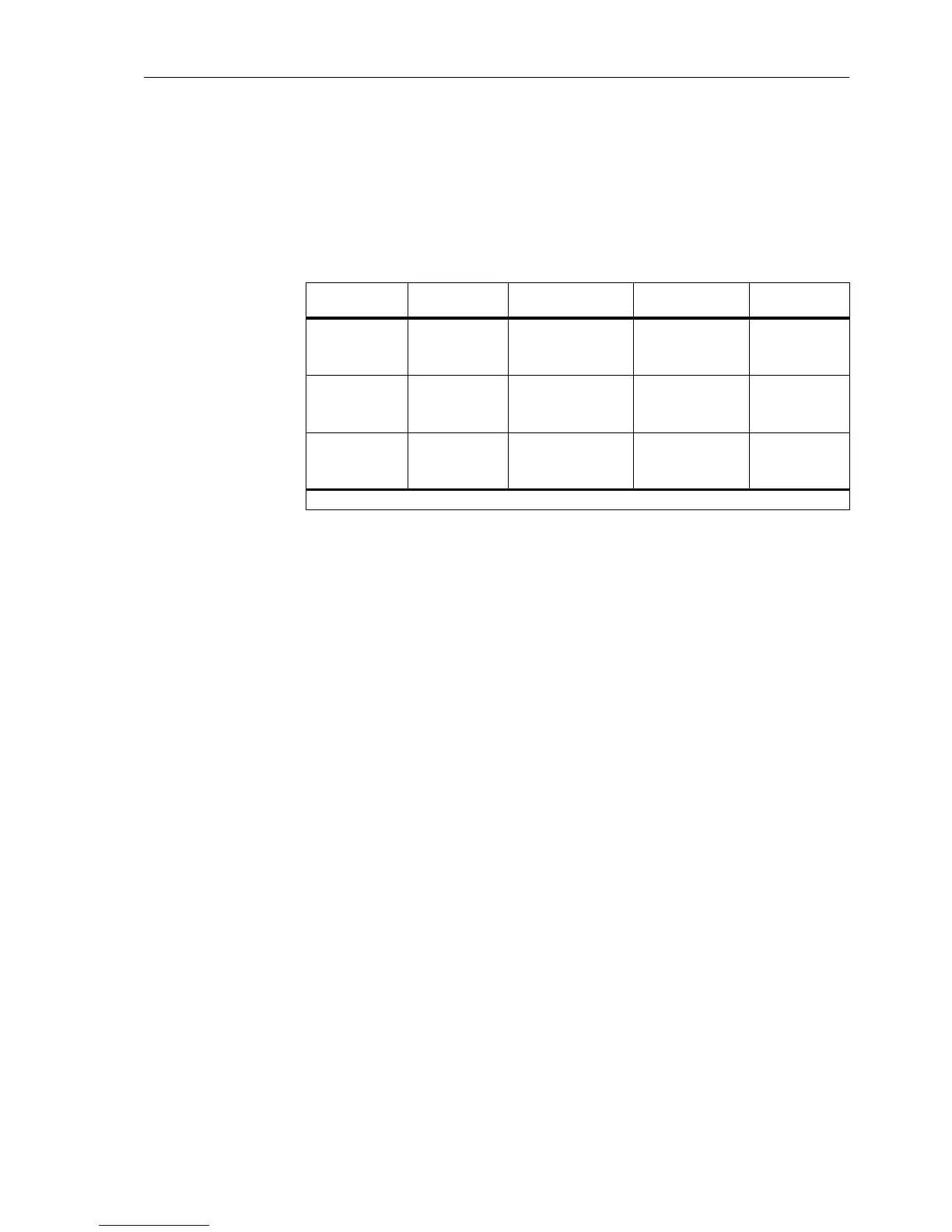
Table 6-2 Loop and phase indication for single–phase overcurrent pick-up
Pick-up
module
Earth-fault de-
tection
Parameter
1Ph FAULTS.
Valid
loop
Signalled
phase(s)
L1
L2
L3
no
no
no
phase–phase
L3–L1
L1–L2
L2–L3
L1, L3
L1, L2
L2, L3
L1
L2
L3
no
no
no
phase–earth
1
)
L1–E
L2–E
L3–E
L1
L2
L3
L1
L2
L3
yes
yes
yes
any
L1–E
L2–E
L3–E
L1, E
L2, E
L3, E
1
) Only possible in earthed networks
 Loading...


