Installation and Commissioning
8-50 7SA6 Manual
C53000-G1176-C156-2
8.3.3 Checking the Binary Inputs and Outputs
Preliminary Notes The binary inputs, outputs, and LEDs of a SIPROTEC
®
4 device can be individually
and precisely controlled using DIGSI
®
4. This feature is used to verify control wiring
from the device to plant equipment during commissioning. This test feature shall
not
be used while the device is in service on a live system.
Note: After termination of the hardware test, the device will reboot. Thereby, all annun-
ciation buffers are erased. If required, these buffers should be extracted with DIGSI
®
4
prior to the test.
The hardware test can be done using DIGSI
®
4 in the online operating mode:
G Open the Online directory by double-clicking; the operating functions for the de-
vice appear.
G Click on Test; the function selection appears in the right half of the screen.
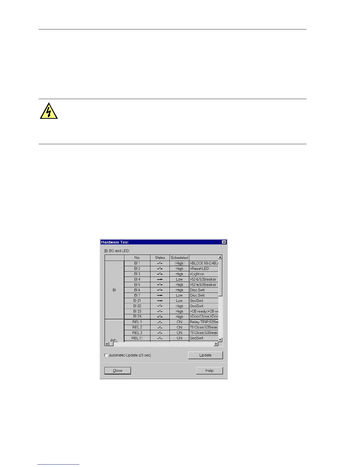
G Double-click in the list view on Hardware Test. The dialogue box of the same
name opens (see Figure 8-26).
Figure 8-26 Dialogue box for hardware test — example
Structure of the
Test Dialogue Box
The dialogue box is divided into three groups: BI for binary inputs, REL for output
relays, and
LED for light-emitting diodes. Each of these groups is associated with an
DANGER!
Changing the status of a binary input or output using the test feature of DIGSI
®
4
results in an actual and immediate corresponding change in the SIPROTEC
®
de-
vice. Connected equipment such as circuit breakers or disconnectors will be
operated as a result of these actions!
 Loading...


