Installation and Commissioning
8-537SA6 Manual
C53000-G1176-C156-2
8.3.5 Checking the Communication Topology
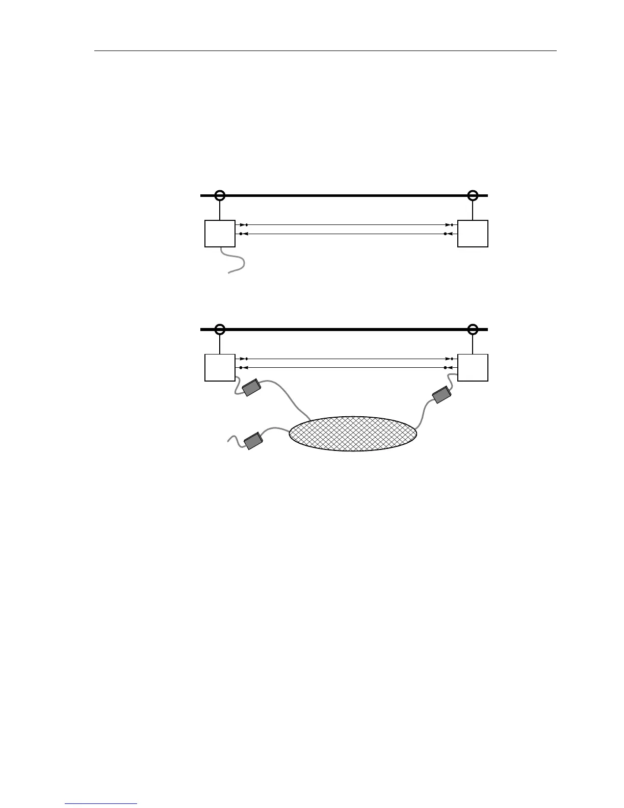
General The communication topology can either be checked from the PC using DIGSI® 4.
You can either connect the PC to the device locally using the operator interface at the
front, or the service interface at the back of the PC (Figure 8-27). Or you can log into
the device using a modem via the service interface (example in Figure 8-28).
I
Figure 8-27 PC interfacing directly to the device - example
Figure 8-28 PC interfacing via modem - example
Checking a
Connection using
Direct Link
For two devices linked with fibre optical cables (as in Figure 8-16 or 8-17), this con-
nection is checked as follows. If two or more device are linked or, if two devices have
been (double-) linked with a ring topology, first check only one link.
o Both devices at the link ends have to be switched on.
o Check in the Event Log (see also Subsubsection 7.1.1.2) or spontaneous annuncia-
tions (see Subsubsection 7.1.1.7) for the following:
G If the message "PI1 with" (protection data interface connected with FNo. 3243)
is provided with the device index of the other device, a link has been established
and one device has recognized the other.
o In the event of a communication link error the message "PI1 Data fault"(FNo.
3229) will be displayed. In this case, check the fibre optical cable link again.
G Have the devices been linked correctly and no cables been mixed up?
G Are the cables free from mechanical damage, intact and the connectors locked?
G Otherwise repeat check.
Proceed with "Consistency of Topology and Parameter Setting".
:
7SA67SA6
:
7SA67SA6
M
o
d
e
m
M
o
d
e
m
M
o
d
e
m
 Loading...


