5-47
4st 9.9/15/20 2008
Connecting Rod Bolts :
First Tightening Torque : 6 N · m (4 lb · ft) [0.6 kgf · m]
SecondTightening Torque : 12 N · m (9 lb · ft) [1.2 kgf · m]
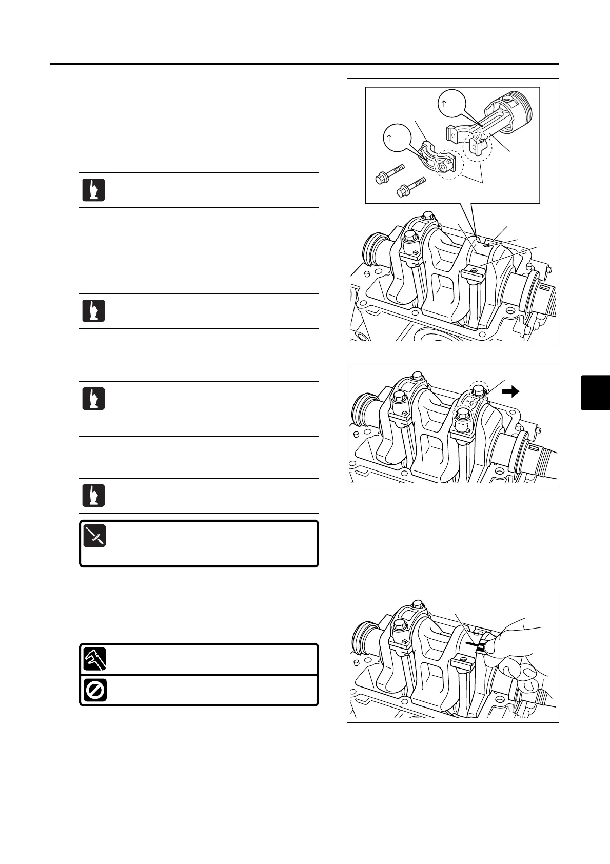
6. Tighten connecting rod bolts in two steps to specified torque.
36)
Inspection of Crank Pin Oil Clearance
1. Clean connecting rod.
2. Place cylinder block upside down on the work bench. Install
piston 2 to connecting rod 1, and install the assembly to
cylinder block.
3. Install crankshaft on the cylinder block.
4. Place plasti-gauge 3 on each crank pin 4 parallel to
crankshaft.
5. Install connecting rod and cap 2 to crank pin 4.
UP
UP
1
2
a
1
5
3
4
Piston rings are not to be attached to piston.
Do not place plasti-gauge 3 on the oil hole 5 of
crank pin 4.
Do not move connecting rod and crankshaft until
oil clearance measurement is completed.
· Be sure that individual cap is installed to their
original connecting rod.
· Check that "UP" mark b of connecting rod is
at crankshaft flywheel side c.
3
Crank Pin Oil Clearance :
0.015 - 0.041 mm (0.00059 - 0.00161 in)
Functional Limit :
0.060 mm (0.00236 in)
7. Remove connecting rod cap and measure width of crushed
plasti-gauge 3 on each crank pin. Replace connecting rod
or crankshaft if the width is over specified value.
5
E_MFS20C_ch05_090105.qxd 09.1.20 5:25 PM ページ 47

 Loading...