8
8-21
4st 9.9/15/20 2008
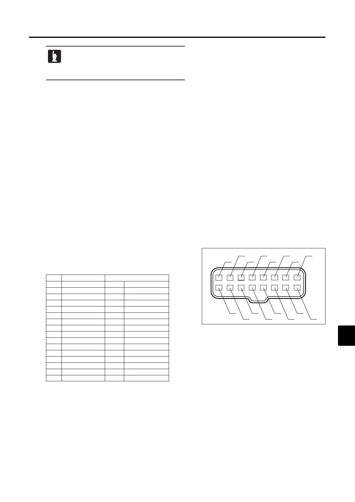
7. CD Unit Coupler
●Check wire harness for disconnection of lead wire and
defective connection.
●Terminals are arranged and numbered as shown.
●The following table shows names of terminals, their
numbers and lead wire colors.
No. Name Lead Wire
1 Ignition (GND) Or Orange
2 Ignition (+) B Black
3 Exciter (H) B/R Black/Red
4 Exciter (L) L Blue
5 Tachometer W White
6 LED power W/R White/Red
7 Vacant
8 Stop Watch Br Brown
9 GND B Black
10 Vacant
11 LED Lg Yellowish Green
12 Pulser (+) R/W Red/White
13 Pulser (-) B Black
14 Vacant
15 Oil Pressure Switch Br/W Brown/White
16 Vacant
Note) 1 It is recommended to use "HIOKI HiTESTER MODEL 3030" for this measurement. Use of other instrument
model for the measurement can cause indication of abnormal value for normal condition, resulting in
inaccurate measurement.
2 Disconnect all connections to measure as an independent unit.
3 Any movement of pointer indicates "ON" or "conductive" state.
4 "CON" means that the pointer moves once and then returned to the value shown in ( ) because of
characteristic of capacitor.
5
The value in ( ) is the condition applied when "1kΩ" range is used. The measurement varies widely among types
of instrument, situations (such as inner power supply), or measurement ranges due to diodes used in the unit.
· Measurement condition Circuit tester to be
used : HIOKI3030
Measurement Range : 1kΩ
· Permissible Error of Resistance : ±20%
E_MFS20C_ch08_081203.qxd 09.1.20 5:33 PM ページ 21

 Loading...