8-20
Electrical System
4st 9.9/15/20 2008
Alternator (Charge Coil) Resistance
: Reference Value (at 20°C)
White (W) – Yellow (Y)
0.27- 0.41 Ω
6. Battery Charging System
1) Inspection of Charge Coil
1. Remove wire band 1 of cable that comes from alternator
located in the rectifier.
2. Disconnect cable coupler from charge coil, and measure
resistance.
This test can be made without removing parts.
2) Inspection of Rectifier
●Check wire harness for disconnection of lead wire and
defective connection.
●Check conductivity between each point by referring to the
following table. Value in ( ) is reference value.
●Perform the measurement with all connections
disconnected to make the component a separated unit.
Rectifier Tester Check Chart
Tester Lead Positive (+) Side (Red)
Red White Black Yellow
RWB Y
Red OFF OFF OFF
R
White ON ON ON
W (3.4Ω) (2.3kΩ) (4.6kΩ)
Black ON ON ON
B (4.6kΩ) (2.2kΩ) (2.2kΩ)
Yellow ON ON ON
Y (3.4kΩ) (4.6kΩ) (2.3kΩ)
Tester Lead Negative (-) Side
(Black)
This test can be made without removing parts.
"ON" means "conductive", and "OFF"
means "non-conductive".
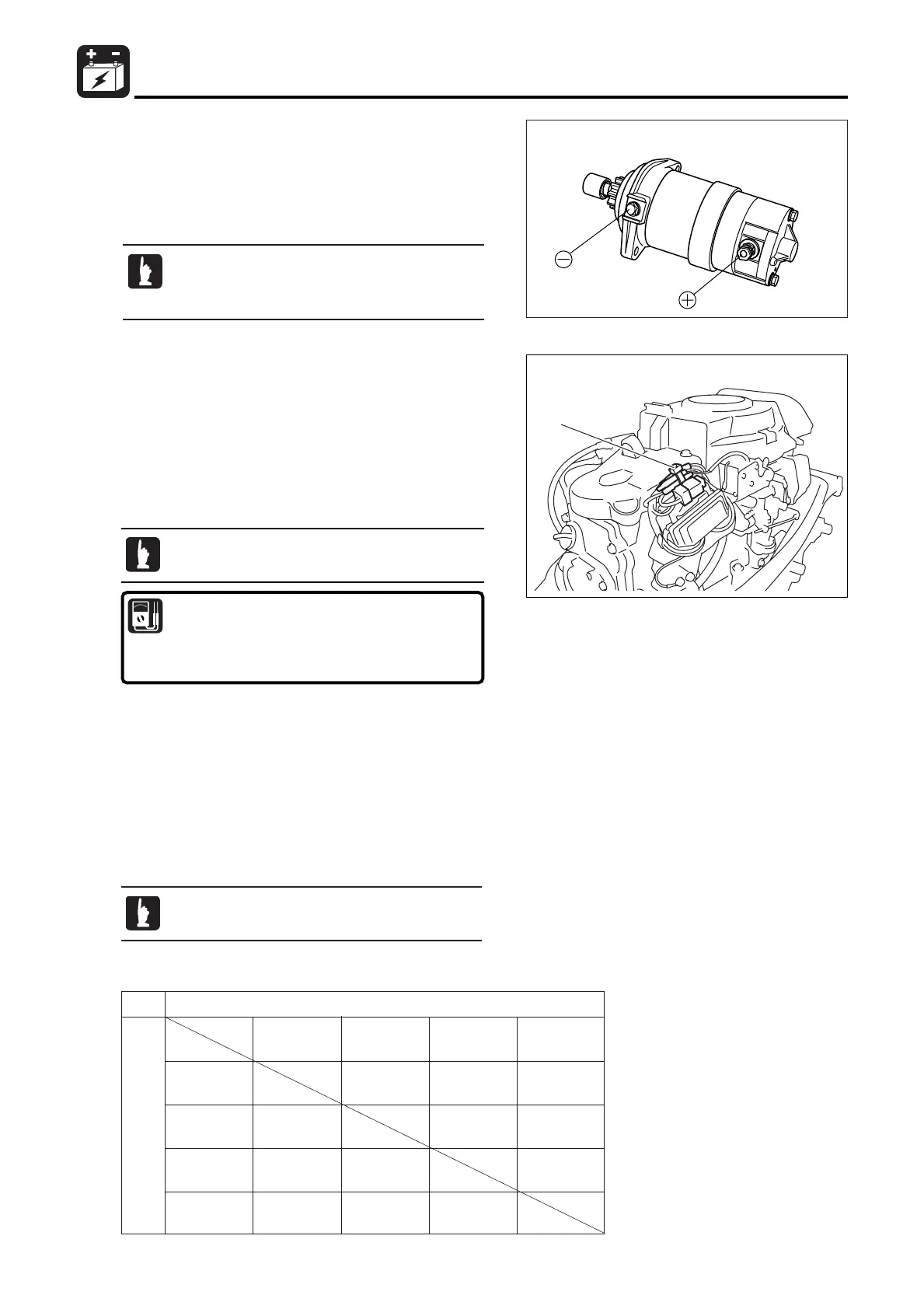
7) Inspection of Starter Motor
Operation
1. Assemble starter motor, and check, before and after
installing it on the power unit, by applying voltage between
points "+" and "-" that it operates normally.
Energizing starter motor produces sparks, and
thus, any inflammable matter must be kept
away from the motor.
E_MFS20C_ch08_081203.qxd 09.1.20 5:33 PM ページ 20

 Loading...