HYDRAULIC SYSTEM
4-17Z580/Z593/Z595 Diesel Service Manual
4
Wheel Motor Replacement
Wheel Motor Removal
37. Install the negative battery cable.
38. Lower the seat.
39. Purge the hydraulic system. Refer to “Purging the
Hydraulic System” on page 4-24.
40. Adjust the control handle neutral position. Refer to
“Adjusting the Control Handle Neutral Position” on
page 4-25.
41. Adjust the hydrostatic pump neutral. Refer to “Set-
ting the Hydrostatic Pump Neutral” on page 4-27.
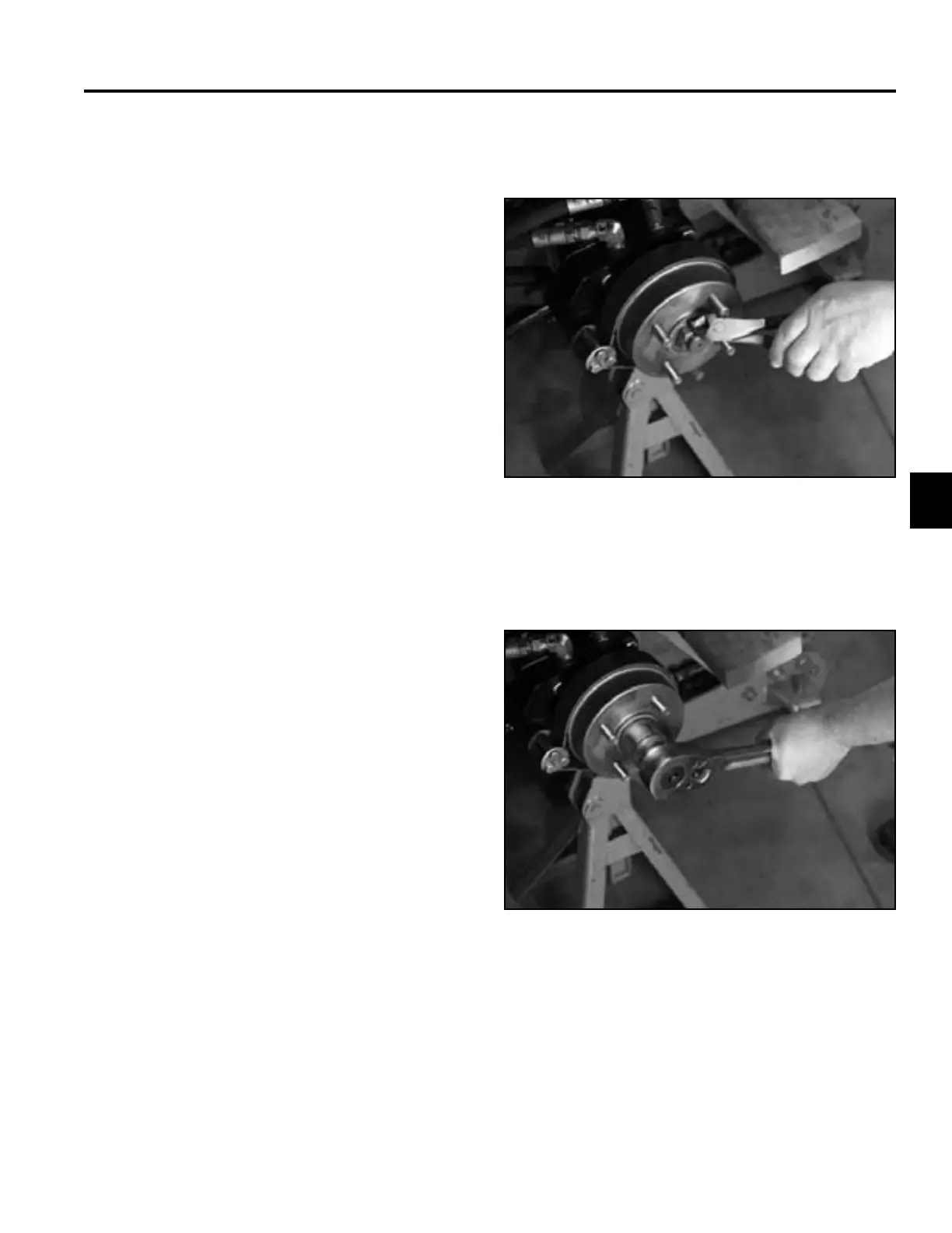
6. Remove the castle nut securing the wheel hub to the
wheel motor (Fig. 299).
Fig 299 PICT-3351
The following procedures are the same for the left and
right wheel motors.
5. Apply the parking brake. Remove the cotter pin from
the wheel motor shaft (Fig. 298).
1. Park the machine on a level surface, disengage the
PTO, turn the ignition off and remove the key.
2. Raise the seat.
3. Remove the negative battery cable from the battery.
4. Support the unit on jack stands and remove the rear
wheel.
Fig 298 PICT-3350

 Loading...