ELECTRICAL
6-10 Z580/Z593/Z595 Diesel Service Manual
6
How It Works Testing
The seat delay module circuit board is made up of sev-
eral different electrical components, such as a transient
voltage suppressor, capacitor, transistors, carbon fi lm
resistors, diodes and a relay. These all work together
to supply seat switch temporary voltage to the circuit to
keep the engine running in case of short term voltage
interruption (Fig. 664).
1. Raise the seat and disconnect the seat switch.
Install a jumper wire in place of the seat switch (Fig.
665).
Fig 664 CLR DSC-2532
Fig 665 PICT-4156a
2. Remove the 4 bolts to the control panel and raise
the panel.
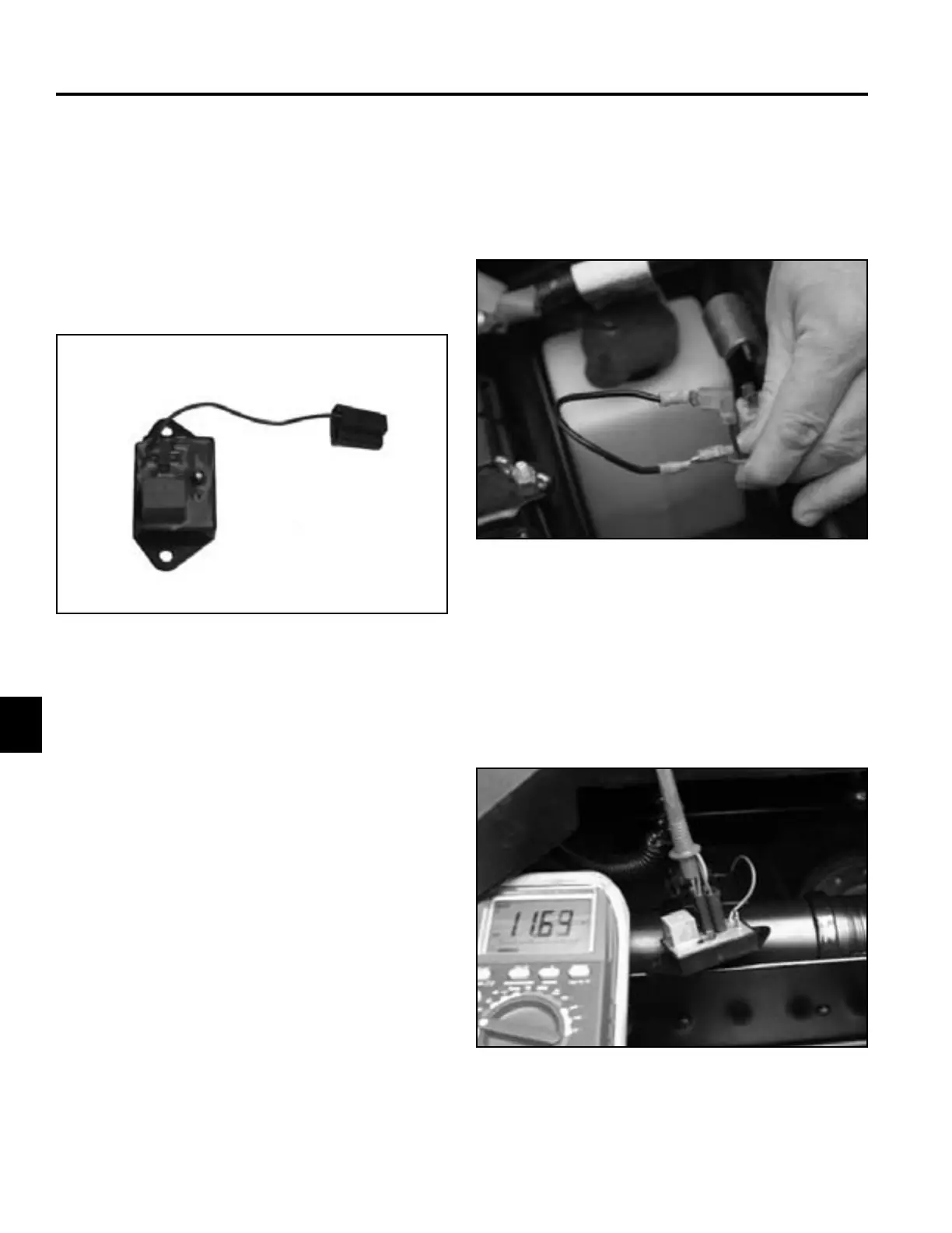
3. Connect a VOM positive lead to the violet wire on
the module (Fig. 666). Connect the negative lead to
the battery negative terminal.
Fig 666 PICT-4153

 Loading...