HYDRAULIC SYSTEM
4-8 Z580/Z593/Z595 Diesel Service Manual
4
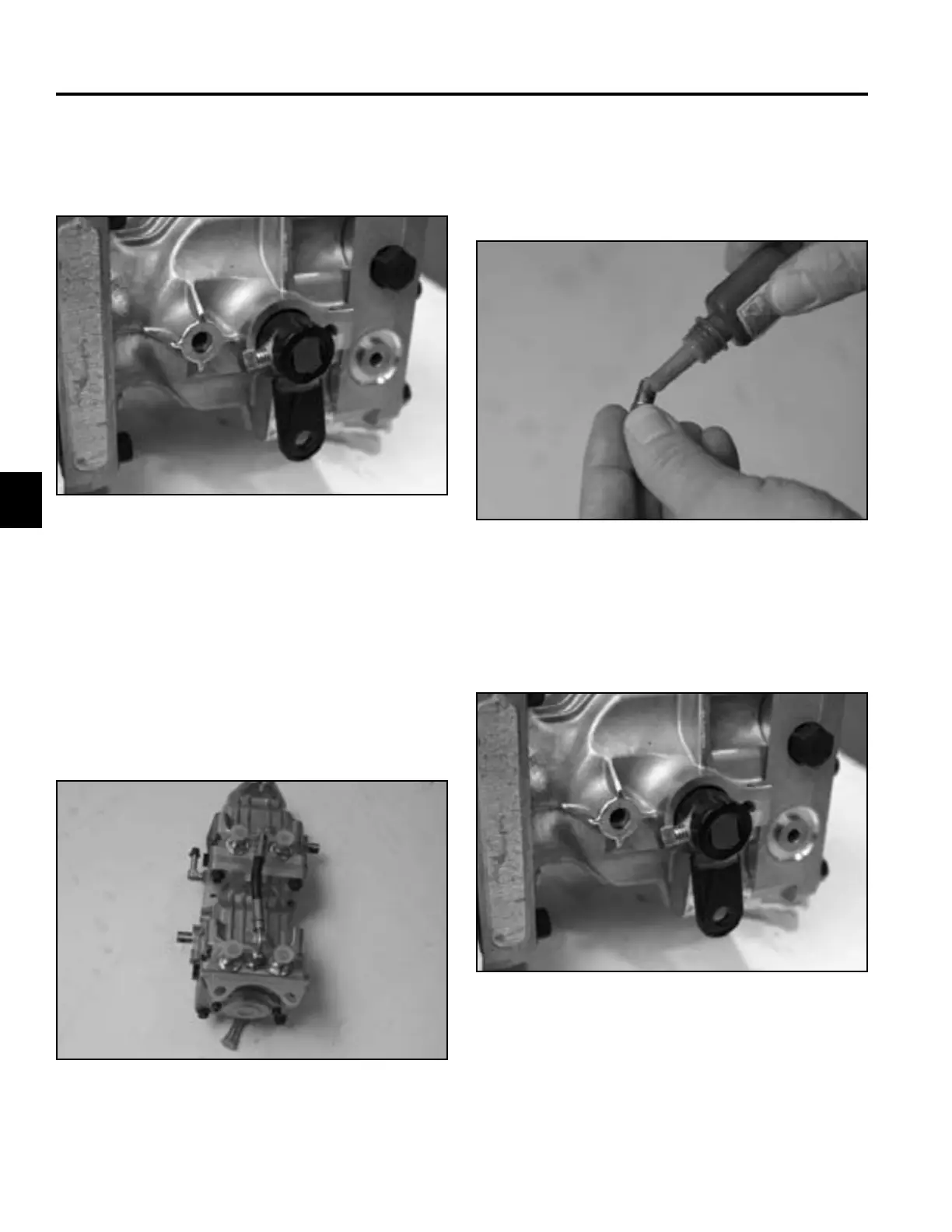
Hydrostatic Tandem Pump Installation
33. Remove the set screw securing the control arm to
the pump control shaft. Remove the control arm from
the pump control shaft (Fig. 264).
1. Apply thread locking compound to the pump control
arm set screw (Fig. 266).
Fig 264 PICT-3302
Fig 266 PICT-3307a
2. Thread the set screw into the control arm. Slide a
control arm onto the pump control shaft and tighten
the set screw (Fig. 267).
34. Repeat steps 29 and 30 to remove the opposite
control arm from the pump.
35. For tandem pump service, refer to the Hydro-Gear
P Series Pumps Service and Repair Manual (form
BLN-52503)
36. Transfer all fi ttings and markings to the new hydro-
static tandem pump (Fig. 265).
Fig 267 PICT-3302
Fig 265 PICT-3305a

 Loading...