ELECTRICAL
6-18 Z580/Z593/Z595 Diesel Service Manual
6
How It Works
Testing
Clutch Coil Continuity Test
The PTO clutch is composed of three major compon-
ents; the fi eld, the clutch plate, and the friction plate.
The clutch plate always turns with the engine. The
fi eld is a coil of wire wound around an iron core, which
acts like an electromagnet when power is applied. The
friction plate is the only piece that can slide inward and
outward on the crankshaft axis. It is spring loaded away
from contact with the clutch plate. When the clutch is
not energized, the clutch plate rests against the brake
material opposite the clutch plate. When energized the
friction plate is drawn into the clutch plate magnetically
and the two rotate as one component.
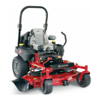
5. The meter should read:
Warner clutch: 1.0 – 2.7 ohms,
Ogura clutch: 2.4 ohms
If the reading is above or below these readings, the
fi eld has failed and needs to be replaced. If the reading
falls within the specifi ed resistance, measure clutch coil
continuity (see below).
This test can be performed the same way on both the
Warner and Orgura clutches.
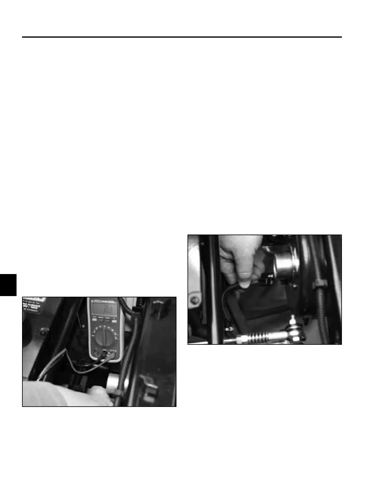
1. Disengage PTO.
2. Raise the seat and disconnect the negative battery
cable from the battery.
3. Unplug the harness connector from the clutch (Fig.
681).
1. Disengage the PTO, set the parking brake, turn the
ignition to the “off” position and remove the ignition
key. Disconnect negative battery cable.
2. Disconnect the clutch harness from the main
harness.
3. Set the multimeter or volt/ohm meter to check
resistance (ohms).
4. Connect the meter lead wires to the clutch wires as
shown (Fig. 680).
Fig 681 PICT-3933
Fig 680 IMG_8116
 Loading...