08/2012
2-4
WorkCentre 5021/5019
2.1.2, 2.1.3
Initial Issue
Status Indicator RAPs
3. Releasing the [ID Card Copy] button returns the display to the Error Code.
2.1.3 Glossary
The following terminology are used throughout the troubleshooting section. The meaning of
these terminology must be fully understood when performing problem analysis.
Common terms:
• Fault Code
This 6-digit code appears when the machine has found problems.
• Actuate (Deactuate)
To mechanically push (release) the Actuator of the switch or the connected mechanical
linkage.
•Block
To place a sheet of document or paper on the photo sensor surface for detection.
• Check
To visually check for operation failure of parts such as relay or mechanical linkage, and
the failure status of the parts.
• Enter the CE Mode
To enter the CE Mode by following the procedure described in 'How to Enter/Exit the CE
Mode' of Chapter 6.
• Check the connection for short circuit
Turn the power OFF. Measure the resistance between the wire and the frame using the
ohm range of a tester.
• Check the connection for open circuit
Turn the power OFF. Measure the resistance between both ends of the wire using the
ohm range of a tester.
• Input Check [xxx-xxx]/Output Check [xxx-xxx]
To enter the Component Check by following the procedure described in 'How to Use the
CE Mode' of Chapter 6.
• Analog Monitor [xxx-xxx]
To enter the Analog Monitor by following the procedure described in 'How to Use the CE
Mode' of Chapter 6.
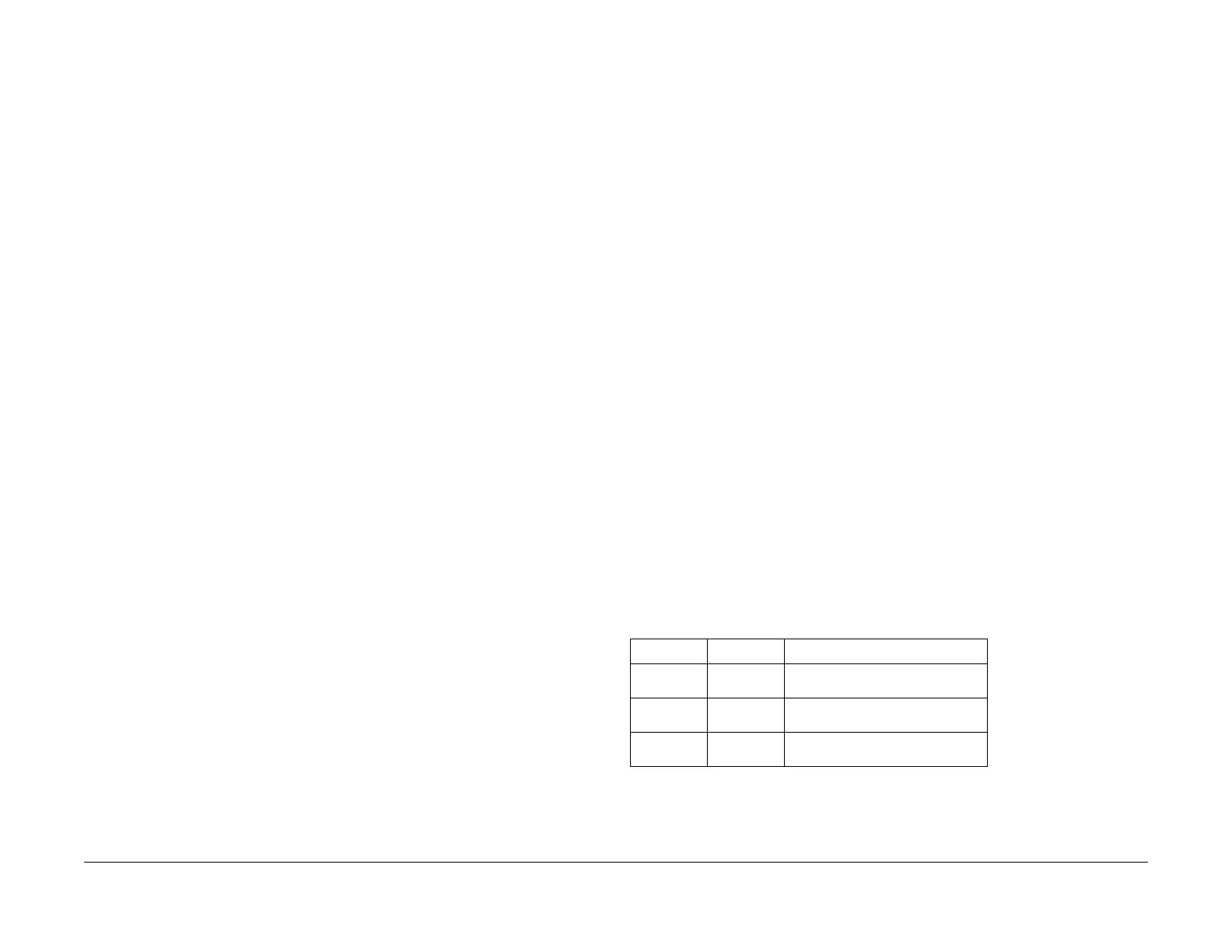
• Check the voltage level
• PL 4.2
Refer to PL 4.2 in Chapter 5 Parts List.
• CH 6.2 Zone J4
Table 1
Voltage Level Range
+3.3VDC (H)
(L)
+3.2 to +3.6VDC
0.0 to +1.0VDC
+5VDC (H)
(L)
+4.8 to +5.4VDC
0.0 to +1.0VDC
+24VDC (H)
(L)
+23.3 to +25.7VDC
0.0 to +3.0VDC

 Loading...