08/2012
5-5
WorkCentre 5021/5019
5.1.4, 5.1.5
Parts List
Initial Issue
5.1.5 Using Parts Navigation
This section describes how to use the Navigation screen (illustrated)
The Navigation screen is divided into two layers, under which there is another layer of PLs.
• The first (top) layer
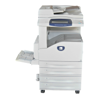
• Navi 1.1(Processor + Option)
The whole processor including DADF and Finisher is illustrated each for good
understanding. Find the module which includes the desired part and click on
Navi 2.X or PL shown at the end of the call out. Navi 2.X shows there is a more
detailed illustration of the module. Otherwise, you will be directly linked to the
applicable PL.
• The second layer
• Navi 2.1 to 2.5
The module found in Navi 1.1 is divided into more modules, which link to the
related PLs. The screen here uses PLXX to show all the parts in the detailed
module. Click on the applicable item, and you will see the illustration of the
applicable PL. Find the desired part in the PL illustration to learn the part's
item no. After that, obtain the appropriate part no. from the list.
On E-DOC, clicking on the item no. makes the List screen displayed. Then the
appropriate part no. can be found.
• The third (bottom) layer has PLXXs.
<Returning from the lower layers to the higher layer>
Clicking on Navi 2.X or PLXX on the upper left of the illustration makes you
return to Navi 1.1 for Processor parts.
Figure 5 5006
This symbol shows the whole area of the framed illustration has not
been modified by the number in the circle. The area still has the previ-
ous configuration.
Figure 6 4001
The Item pointed to by this symbol in the illustration is modified by the
number in the circle. The item has the modified configuration.
Figure 7 4002
The Item pointed to by this symbol in the illustration has not been modi-
fied by the number in the circle. The item still has the previous configu-
ration.
with 5V This symbol in the DESCRIPTION column shows the part is modified
by the number. The part has the modified configuration.
(w/o 5V) This symbol in the DESCRIPTION column shows the part has not been
modified by the number. The part still has the previous configuration.
(ISC) MCU/ESS
PWB
ISC followed by part name in the DESCRIPTION column represents
Important Information Stored Component that stores important cus-
tomer information. To replace and discard an ISC, follow the procedure
for it described in chapter 4.
Table 1
Terminology and
Symbols Description
 Loading...
