08/2012
7-27
WorkCentre 5021/5019
1., 2.
Wiring Data
Initial Issue
1. How to Use BSDs
1. Enter the Chain directed in the Troubleshooting chapter.
2. Or enter the appropriate Chain by referring to the contents.
3. Diagnose the failure in the appropriate Chain, using test data.
4. If where the failure has occurred can be located, refer to the Parts List No. or Adjustment
No. on the location to go to the index of parts or the appropriate adjustment.
WARNING
Turn off the Main Power Switch and disconnect the Power Cord from the wall outlet
before removing /installing any part.
Otherwise, there would be a danger of electrical shock or injury.
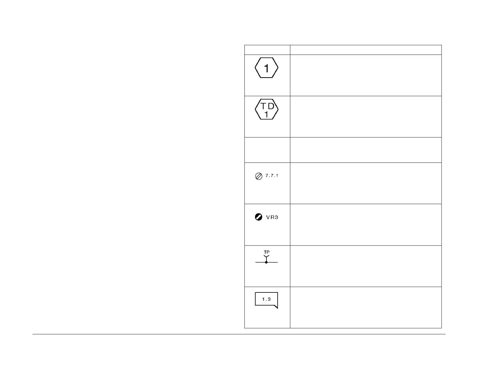
2. Explanation of Symbols
Table 1
Symbol Description
Figure 1 9050
This symbol is used to refer to Notes usually described on the same
page.
Figure 2 9051
This symbol is used to refer to test data usually on the same page for
reference in case the voltage value shown on the BSD id different
from the measured value.
PL 7.7 This symbol is used to refer to the Parts List. PL stands for Parts List
and 7.7 denotes Plate No. This shows the appropriate part is shown
on the indicated plate. This symbol is added to all the replaceable
parts on the BSD.
Figure 3 9053
This symbol is used to refer to the adjustments in the Repair and
Adjustment chapters. The number 7.7.1 shows the adjustment proce-
dure is found as ADJ 7.7.1 in the Adjustment chapter.
Figure 4 9054
This symbol identifies a variable resistor adjustable in the field.
Figure 5 9061
This symbol identifies a test point of a signal.
Figure 6 9055
This symbol is used to show where the input into the functions comes
from. This example shows the input comes from the Group Functions
in Chain 1-3.

 Loading...