08/2012
2-62
WorkCentre 5021/5019
2.2.4.7, 2.2.4.8
Initial Issue
Status Indicator RAPs
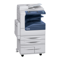
2.2.4.7 Motor Left Running Failure FIP
Procedure
Figure 1 2005
Turn OFF the power. Disconnect the PWB connector. Is the resistance between the con-
nector pin-3 and the frame 10Ohm or less?
YN
Replace the PWB.
Check the connection between the connector pin-3 and the motor pin-2 for a short circuit.
If no problems are found, replace the motor.
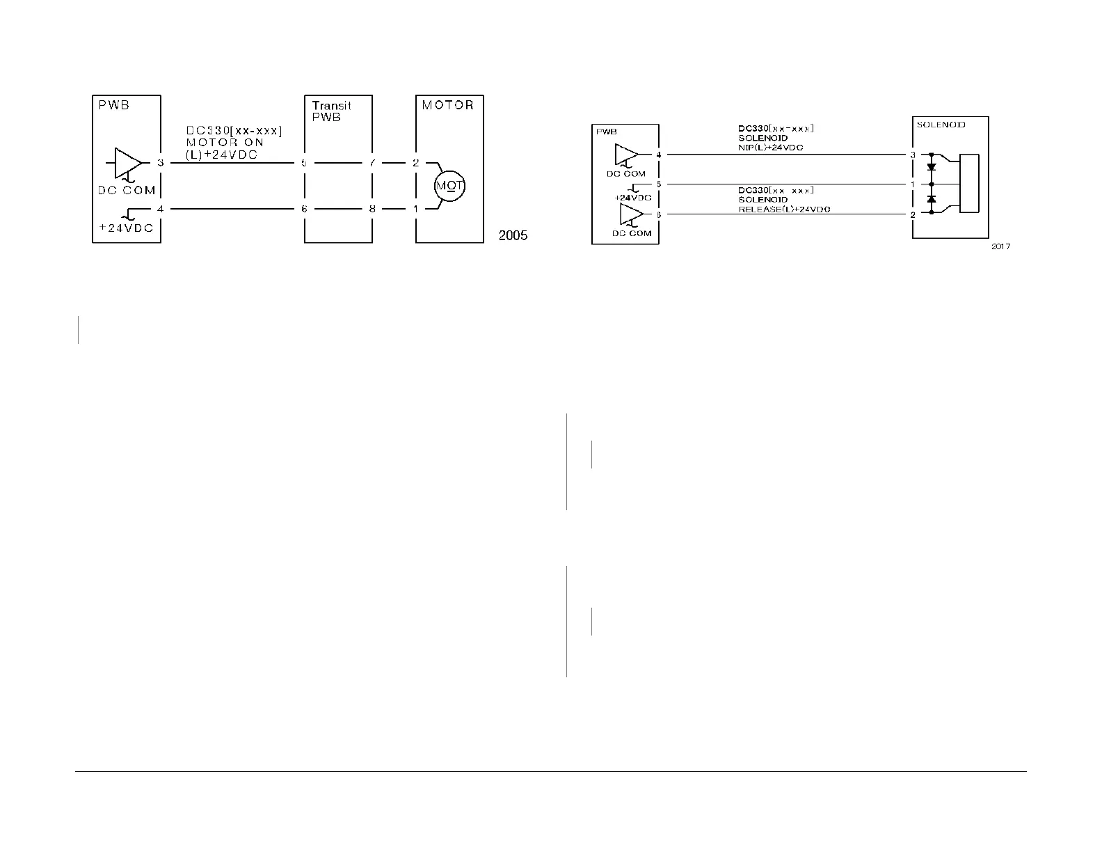
2.2.4.8 NIP/RELEASE SOLENOID Not Energized Failure
FIP
Procedure
Figure 1 2017
NOTE: Before performing this FIP, ensure that there is no (mechanical) operation failure with
the solenoid.
Is +24VDC measured between the NIP/RELEASE SOLENOID pin-1 (+) and the GND (-)?
YN
Is +24VDC measured between the PWB pin-5 (+) and the GND (-)?
YN
Check the +24VDC inputs of the PWB. If no problem is found, replace the PWB.
Check the connection between the PWB pin-5 and the NIP/RELEASE SOLENOID pin-1
for an open circuit and poor contact.
Use the following FIP when there is a problem with the NIP.
Enter DC330[XXX-XXX] and turn the SOL NIP ON. Is +24VDC measured between the PWB
pin-4 (+) and the GND (-)?
YN
Enter DC330[XXX-XXX] and turn the SOL NIP ON. Is +24VDC measured between the
NIP/RELEASE SOLENOID pin-3 (+) and the GND (-)?
YN
Replace the NIP/RELEASE SOLENOID.
Check the connection between the PWB pin-4 and the NIP/RELEASE SOLENOID pin-3
for an open circuit and poor contact.
Use the following FIP when there is a problem with the RELEASE.
Enter DC330[XXX-XXX] and turn the SOL RELEASE ON. Is +24VDC measured between
the PWB pin-6 (+) and the GND (-)?

 Loading...