EasyManuals Logo
Home>Xerox>All in One Printer>WorkCentre 5021

Xerox WorkCentre 5021 Service Documentation

Xerox WorkCentre 5021
457 pages
To Next Page IconTo Next Page
To Previous Page IconTo Previous Page
Page #413 background imageLoading...
Page #413 background image
08/2012
7-30
WorkCentre 5021/5019
2., 3.
Initial Issue
Wiring Data
3. Signal Name
Signal Name Structure
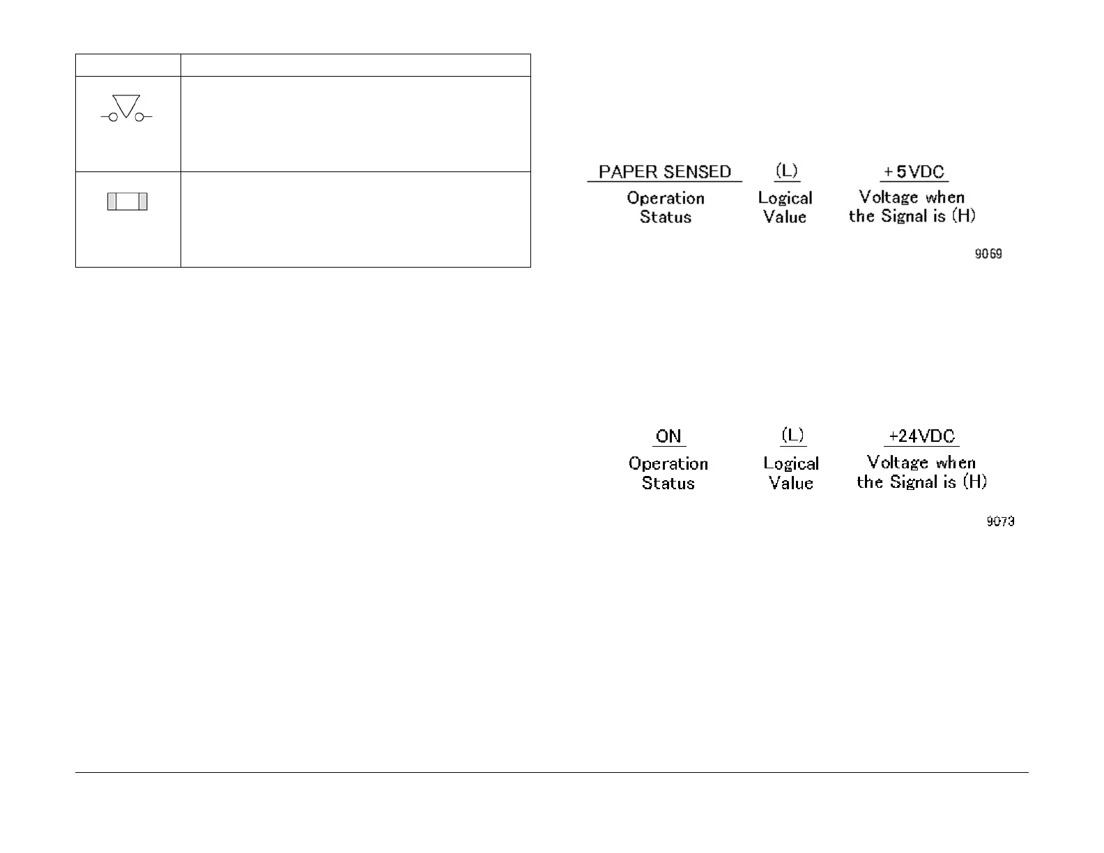
• Input Component
Figure 1 9069
The example indicates that when paper is sensed, the signal level is (L) and that when
paper is not sensed, the signal level is (H) with the voltage +5VDC.
• Output Component
Figure 2 9073
The example indicates that when the component is ON, the signal level is (L) and that
when it is OFF, the signal level is (H) with the voltage +24VDC.
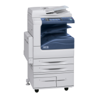
Figure 35 9076
This symbol shows the Cheater type of Interlock Switch.
Figure 36 9077
This symbol shows the Chip Fuse.
Table 1
Symbol Description

Table of Contents

Other manuals for Xerox WorkCentre 5021

Questions and Answers:

Question and Answer IconNeed help?

Do you have a question about the Xerox WorkCentre 5021 and is the answer not in the manual?

Xerox WorkCentre 5021 Specifications

General IconGeneral
BrandXerox
ModelWorkCentre 5021
CategoryAll in One Printer
LanguageEnglish

Related product manuals