EasyManua.ls Logo

ABB ACS355 User Manual

ABB ACS355
406 pages
To Next Page IconTo Next Page
To Previous Page IconTo Previous Page
Page #100 background imageLoading...
Page #100 background image
100 Control panels
Changed parameters mode
In the Changed parameters mode, you can:
view a list of all parameters that have been changed from the macro default
values
change these parameters
start, stop, change the direction and switch between local and remote control.
How to view and edit changed parameters
Step Action Display
1. Go to the Main menu by pressing if you are in the
Output mode, otherwise by pressing repeatedly until
you get to the Main menu.
2. Go to the Changed parameters mode by selecting
CHANGED PAR on the menu with keys and ,
and pressing .
3. Select the changed parameter on the list with keys
and . The value of the selected parameter is shown
below it. Press to modify the value.
4. Specify a new value for the parameter with keys
and .
Pressing the key once increments or decrements the
value. Holding the key down changes the value faster.
Pressing the keys simultaneously replaces the displayed
value with the default value.
5. To accept the new value, press . If the new value
is the default value, the parameter is removed from the
list of changed parameters.
To cancel the new value and keep the original, press
.
MENU
EXIT
PARAMETERS
ASSISTANTS
CHANGED PAR
EXIT
ENTER
00:00
LOC
MAIN MENU 1
ENTER
1202 CONST SPEED 1
10.0 Hz
1203 CONST SPEED 2
1204 CONST SPEED 3
9902 APPLIC MACRO
EXIT
EDIT
00:00
LOC
CHANGED PAR
EDIT
1202 CONST SPEED 1
CANCEL
SAVE
00:00
LOC
10.0 Hz
PAR EDIT
1202 CONST SPEED 1
CANCEL
SAVE
00:00
LOC
15.0 Hz
PAR EDIT
SAVE
CANCEL
1202 CONST SPEED 1
15.0 Hz
1203 CONST SPEED 2
1204 CONST SPEED 3
9902 APPLIC MACRO
EXIT
EDIT
00:00
LOC CHANGED PAR

Table of Contents

Other manuals for ABB ACS355

Question and Answer IconNeed help?

Do you have a question about the ABB ACS355 and is the answer not in the manual?

ABB ACS355 Specifications

General IconGeneral
Input Voltage200 V to 240 V AC, 380 V to 480 V AC
Frequency47 Hz to 63 Hz
Control MethodScalar control
Protection FeaturesOvercurrent, Overvoltage, Undervoltage, Overtemperature, Short circuit
Communication InterfacesModbus RTU, CANopen
Enclosure RatingIP20
Operating Temperature-10°C to +50°C (14°F to 122°F)
Storage Temperature-40°C to +70°C (-40 to +158 °F)
Humidity95% RH (non-condensing)
AltitudeUp to 1000 m (3280 ft) without derating

Summary

Safety

Use of Warnings

Explains warning symbols and their significance for safety.

Planning the Electrical Installation

Selecting the Supply Disconnecting Device

Specifies requirements for the disconnecting means.

Electrical Installation

Connecting the Power Cables

Provides diagrams and procedures for power cable connections.

Installation Checklist

Checking the Installation

A comprehensive checklist for mechanical and electrical installation verification.

Start-up, Control with I/O and ID Run

How to Start Up the Drive

Guides on initiating drive start-up procedures.

Program Features

Start-up Assistant

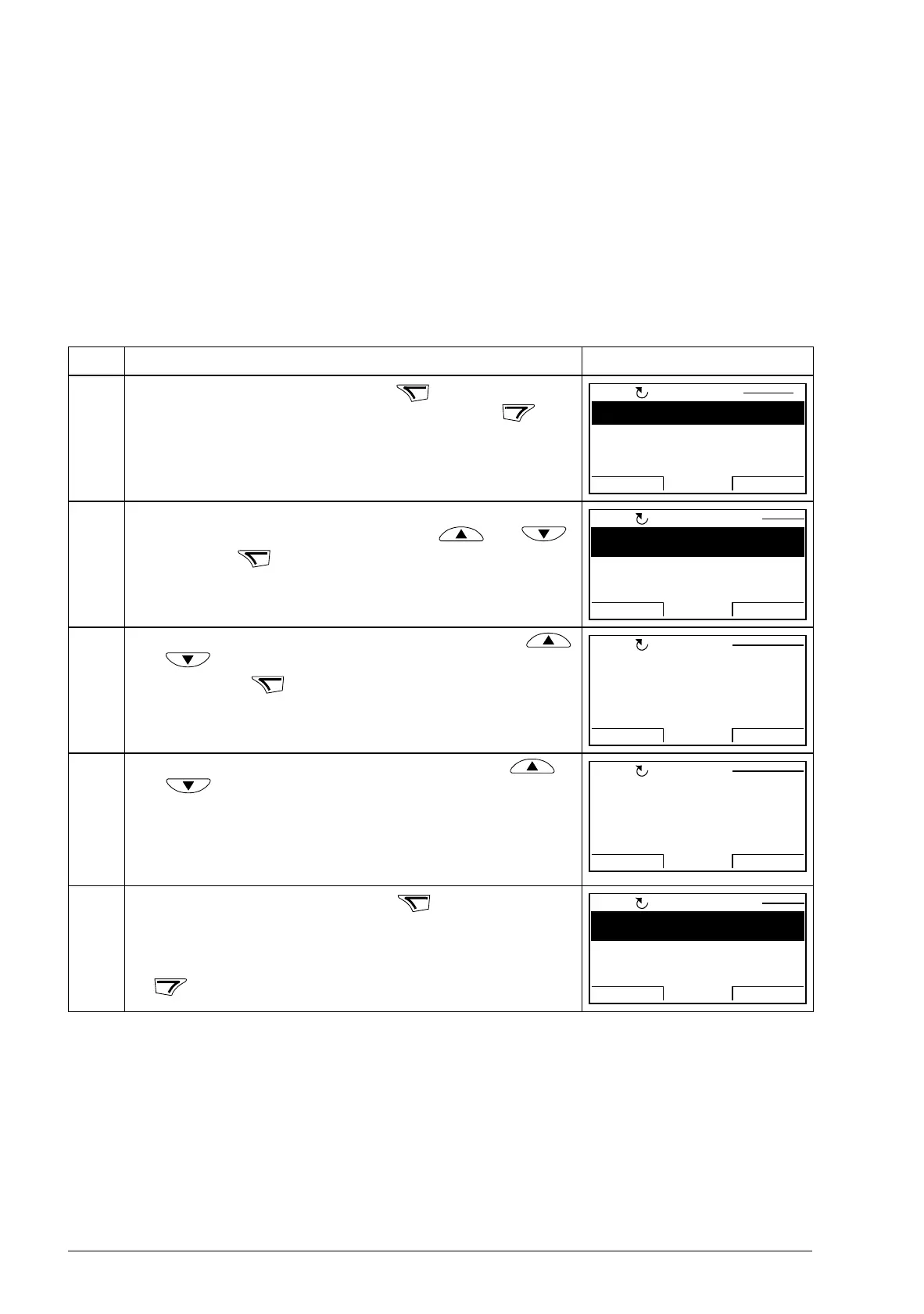
Guides the user through drive start-up with requested data entry.

Fieldbus Control with Embedded Fieldbus

Setting up Communication through the Embedded Modbus

Configuration steps for Modbus communication.

Fieldbus Control with Fieldbus Adapter

Setting up Communication through a Fieldbus Adapter Module

Configuration steps for fieldbus adapter communication.

Fault Tracing

Alarm and Fault Indications

Lists alarm and fault messages, causes, and corrective actions.

How to Reset

Details on how to reset faults and alarms.

Technical Data

Ratings

Presents drive types, input/output ratings, and frame sizes.

Appendix: Resistor Braking

Appendix: Extension Modules

Appendix: Safe Torque Off (STO)

Basics

Explains the fundamental principles of the Safe Torque Off function.

Related product manuals