Application macros 115
Motor potentiometer macro
This macro provides a cost-effective interface for PLCs that vary the speed of the
motor using only digital signals. To enable the macro, set the value of parameter 9902
APPLIC MACRO to 4 (MOTOR POT).
For the parameter default values, see section Default values with different macros on
page 176. If you use other than the default connections presented below, see section
I/O terminals on page 51.
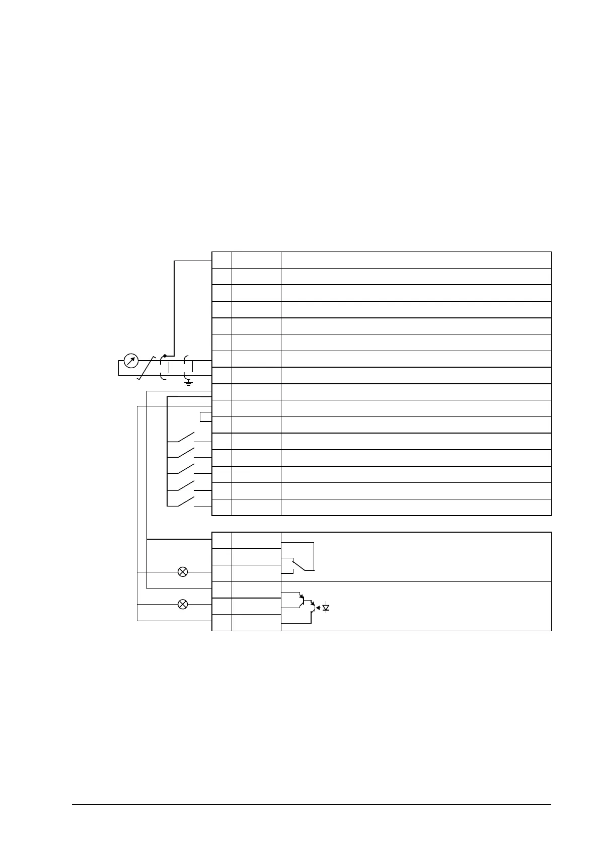
Default I/O connections
X1A
1 SCR Signal cable shield (screen)
2 AI1 Not in use by default. 0…10 V
3 GND Analog input circuit common
4 +10V Reference voltage: +10 V DC, max. 10 mA
5 AI2 Not in use by default. 0…10 V
6 GND Analog input circuit common
7AO Motor speed value: 0…20 mA
8 GND Analog output circuit common
9 +24V Auxiliary voltage output: +24 V DC, max. 200 mA
10 GND Auxiliary voltage output common
11 DCOM Digital input common
12 DI1 Stop (0) / Start (1)
13 DI2 Forward (0) / Reverse (1)
14 DI3 Speed reference up
1)
15 DI4 Speed reference down
1)
16 DI5 Constant speed 1: parameter 1202
X1B
17 ROCOM Relay output 1
No fault [Fault (-1)]
18 RONC
19 RONO
20 DOSRC Digital output, max. 100 mA
No fault [Fault (-1)]
21 DOOUT
22 DOGND
max. 500 ohm
2)
1)
If DI3 and DI4 are both active or inactive, the
speed reference is unchanged.
The existing speed reference is stored
during stop and power down.
2)
360 degree grounding under a clamp.
Tightening torque = 0.4 N·m / 3.5 lbf·in.
Safe torque off connections (X1C:STO; not
shown in the diagram) are jumpered by default.

 Loading...


