54 Electrical installation
Default I/O connection diagram
The default connection of the control signals depends on the application macro in
use, which is selected with parameter 9902 APPLIC MACRO.
The default macro is the ABB standard macro. It provides a general purpose I/O
configuration with three constant speeds. Parameter values are the default values
given in section Default values with different macros on page 176. For information on
other macros, see chapter Application macros on page 109.
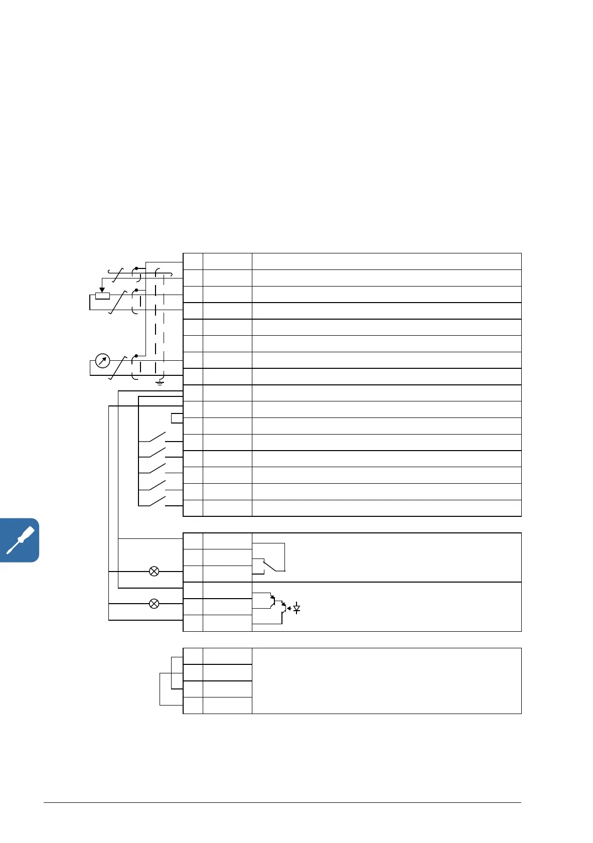
The default I/O connections for the ABB standard macro are given in the figure below.
X1A
1 SCR Signal cable shield (screen)
2AI1 Output frequency reference: 0…10 V
1)
3 GND Analog input circuit common
4 +10V Reference voltage: +10 V DC, max. 10 mA
5 AI2 Not in use by default. 0…10 V
6 GND Analog input circuit common
7AO Output frequency value: 0…20 mA
8 GND Analog output circuit common
9 +24V Auxiliary voltage output: +24 V DC, max. 200 mA
10 GND Auxiliary voltage output common
11 DCOM Digital input common
12 DI1 Stop (0) / Start (1)
13 DI2 Forward (0) / Reverse (1)
14 DI3 Constant speed selection
2)
15 DI4 Constant speed selection
2)
16 DI5 Acceleration and deceleration selection
3)
X1B
17 ROCOM Relay output 1
No fault [Fault (-1)]
18 RONC
19 RONO
20 DOSRC Digital output, max. 100 mA
No fault [Fault (-1)]
21 DOOUT
22 DOGND
X1C:STO
1 OUT1 STO (Safe torque off) connection
2OUT2
3IN1
4IN2
max. 500 ohm
1…10 kohm
4)

 Loading...


