Mechanical installation 35
Fasten clamping plates
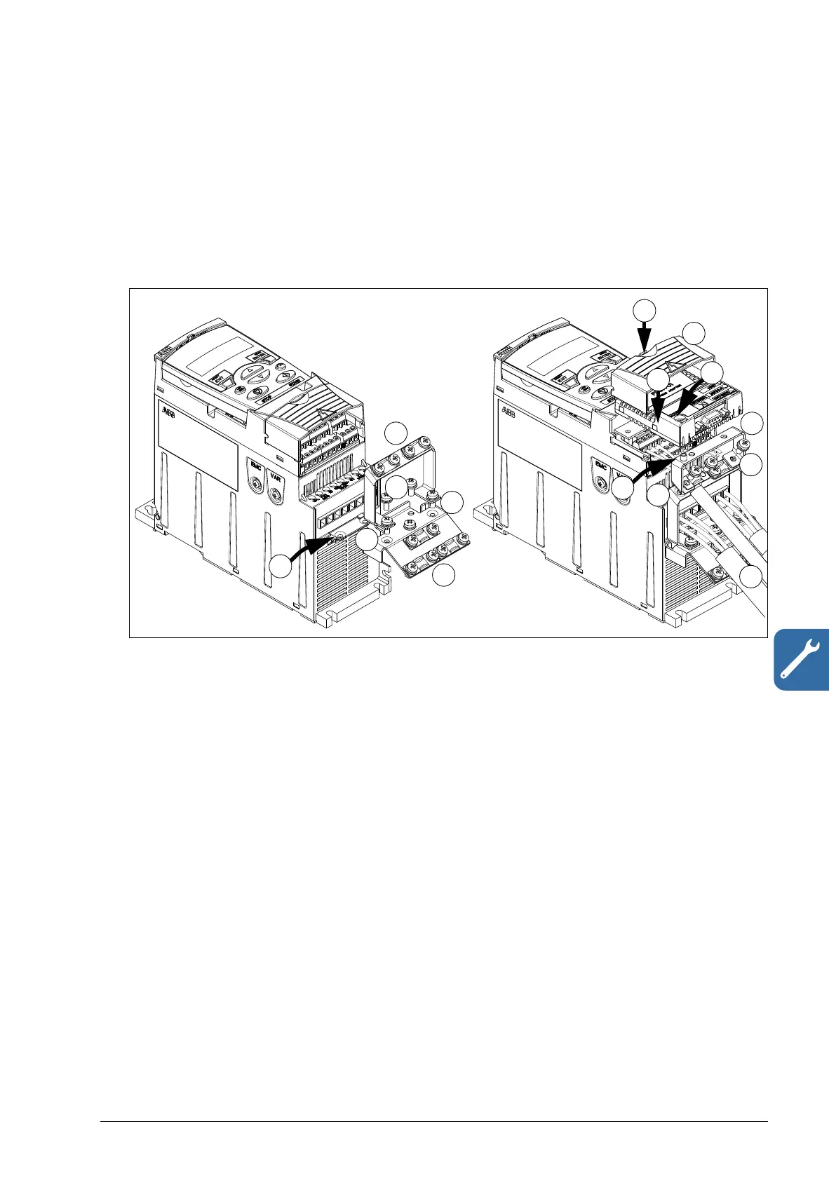
Note: Make sure that you do not throw the clamping plates away as they are required
for proper grounding of the power and control cables as well as the fieldbus option.
1. Fasten the clamping plate (A) to the plate at the bottom of the drive with the
provided screws.
2. For frame sizes R0…R2, fasten the I/O clamping plate (B) to the clamping plate
with the provided screws.
Attach the optional fieldbus module
3. Connect the power and control cables as instructed in chapter Electrical
installation on page 47.
4. Place the fieldbus module on the option ground plate (C) and tighten the
grounding screw on the left corner of the fieldbus module. This fastens the
module to the option ground plate.
5. If the terminal cover is not already removed, push the recess in the cover and
simultaneously slide the cover off the frame.
6. Snap the fieldbus module attached to the option ground plate in position so that
the module is plugged to the connection on the drive front and the screw holes in
the option ground plate and the I/O clamping plate are aligned.
7. Fasten the option ground plate to the I/O clamping plate with the provided screws.
8. Slide the terminal cover back in place.

 Loading...


