364 Technical data
Losses, cooling data and noise
Losses and cooling data
Frame size R0 has natural convection cooling. Frame sizes R1…R4 are provided
with an internal fan. The air flow direction is from bottom to top.
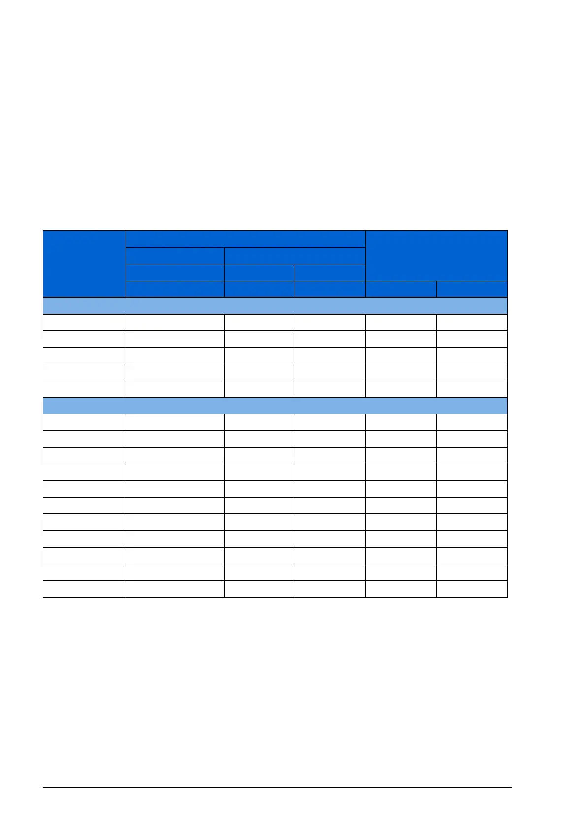
The table below specifies the heat dissipation in the main circuit at nominal load and
in the control circuit with minimum load (I/O and panel not in use) and maximum load
(all digital inputs in the on state and the panel, fieldbus and fan in use). The total heat
dissipation is the sum of the heat dissipation in the main and control circuits.
Type Heat dissipation Air flow
ACS355- Main circuit Control circuit
x = E/U Rated /
1N
and /
2N
Min Max
W W W m
3
/h ft
3
/min
1-phase U
N
= 200…240 V (200, 208, 220, 230, 240 V)
01x-02A4-2 25 6.1 22.7 - -
01x-04A7-2 46 9.5 26.4 24 14
01x-06A7-2 71 9.5 26.4 24 14
01x-07A5-2 73 10.5 27.5 21 12
01x-09A8-2 96 10.5 27.5 21 12
3-phase U
N
= 200…240 V (200, 208, 220, 230, 240 V)
03x-02A4-2 19 6.1 22.7 - -
03x-03A5-2 31 6.1 22.7 - -
03x-04A7-2 38 9.5 26.4 24 14
03x-06A7-2 60 9.5 26.4 24 14
03x-07A5-2 62 9.5 26.4 21 12
03x-09A8-2 83 10.5 27.5 21 12
03x-13A3-2 112 10.5 27.5 52 31
03x-17A6-2 152 10.5 27.5 52 31
03x-24A4- 2 250 16.6 35.4 71 42
03x-31A0-2 270 33.4 57.8 96 57
03x-46A2-2 430 33.4 57.8 96 57

 Loading...


