156 Program features
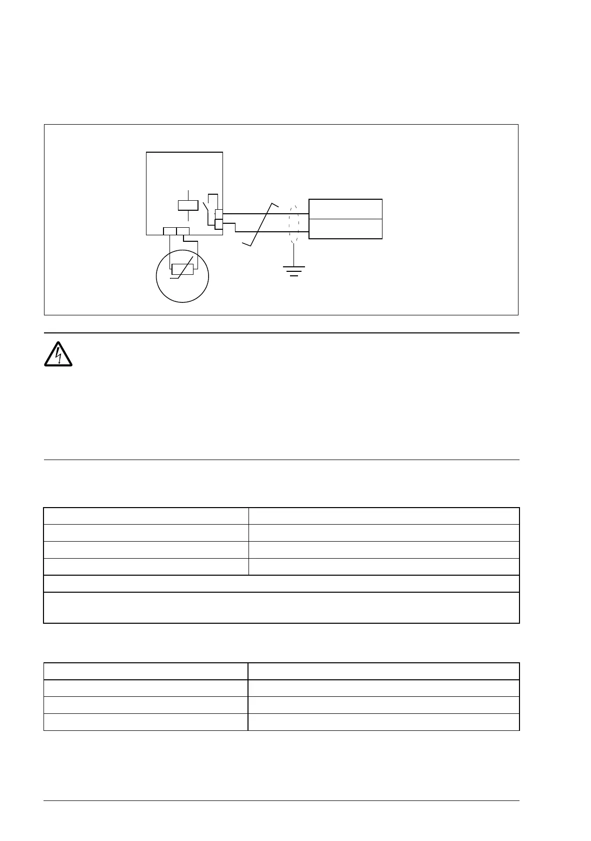
It is also possible to monitor motor temperature by connecting a PTC sensor and
a thermistor relay between the +24 V DC voltage supply offered by the drive and a
digital input. The figure below displays the connection.
WARNING! According to IEC 664, the connection of the motor thermistor to
the digital input requires double or reinforced insulation between motor live
parts and the thermistor. Reinforced insulation entails a clearance and creeping
distance of 8 mm (400/500 V AC equipment).
If the thermistor assembly does not fulfill the requirement, the other I/O terminals of
the drive must be protected against contact, or a thermistor relay must be used to
isolate the thermistor from the digital input.
Settings
Diagnostics
Parameter Additional information
Group 13 ANALOG INPUTS Analog input settings
Group 15 ANALOG OUTPUTS Analog output settings
Group 35 MOTOR TEMP MEAS Motor temperature measurement settings
Other
At the motor end the cable shield should be earthed through, eg a 3.3 nF capacitor. If this is not
possible, the shield is to be left unconnected.
Actual signal Additional information
0145 Motor temperature
Alarm/Fault Additional information
MOTOR TEMP/MOT OVERTEMP Excessive motor temp
T
Thermistor
relay
DI1…5
+24 V DC
Motor
Par. 3501 = THERM(0) or THERM(1)

 Loading...


