Total standby output power (12800) is equal to total active output power (12800).
Device# show power
Power Fan States
Supply Model No Type Capacity Status 1 2
------ -------------------- ---- -------- ------------ -----------
PS1 C9400-PWR-3200AC ac 3200 W active good good
PS2 C9400-PWR-3200AC ac 3200 W active good good
PS3 C9400-PWR-3200AC ac 3200 W active good good
PS4 C9400-PWR-3200AC ac 3200 W active good good
PS5 C9400-PWR-3200DC dc 3200 W standby good good
PS6 C9400-PWR-3200DC dc 3200 W standby good good
PS7 C9400-PWR-3200DC dc 3200 W standby good good
PS8 C9400-PWR-3200DC dc 3200 W standby good good
PS Current Configuration Mode : N+N redundant
PS Current Operating State : Full protected
PS Slots Configured standby : PS5, PS6, PS7, PS8
Power supplies currently active : 4
Power supplies currently available : 8
Power Summary Maximum
(in Watts) Used Available
------------- ------ ---------
System Power 3505 3505
Inline Power 0 9295
------------- ------ ---------
Total 3505 12800
Other valid configuration options for the n+n mode:
• All installed modules are AC-input power supply modules of the same capacity and with the same
AC-input voltage voltage level; n number of modules configured as active and n, as standby.
• All installed modules are DC-input power supply modules of the same capacity; n number of modules
configured as active and n, as standby.
Example:n+nRedundant Mode(Power SupplyModulesof DifferentCapacities
+ Normal Protected State)
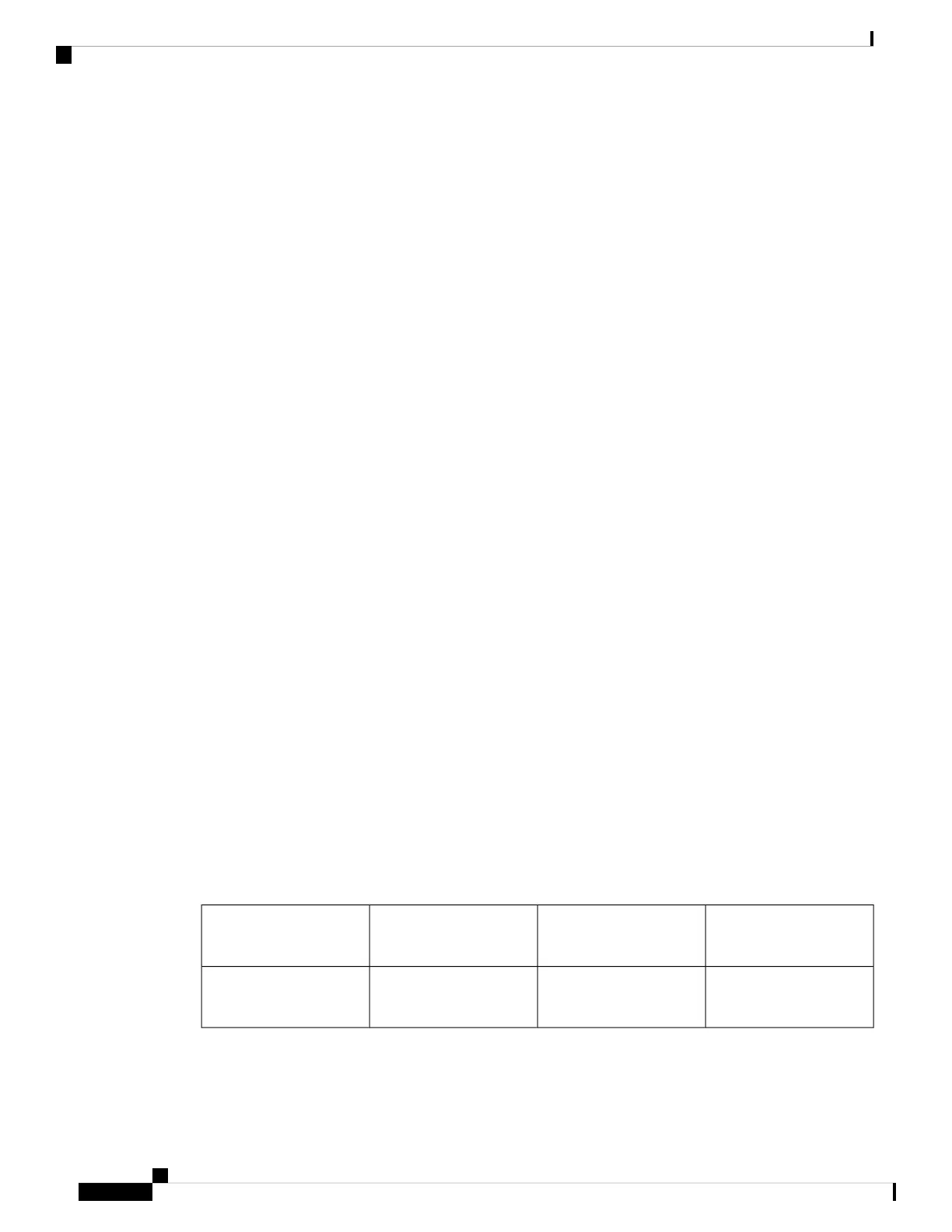
The table below represents the two rows of power supply slots in a Cisco Catalyst 9400 Series chassis. Power
supply slots are indicated as PS1, PS2, and so on. For this example, slots 1 through 4 have AC-input power
supply modules of the same capacity (2100W) and all are configured as active. Slots 5 through 8 have DC-input
power supply modules and all are configured as standby.
PS4 (Active)
C9400-PWR-2100AC
PS3 (Active)
C9400-PWR-2100AC
PS2 (Active)
C9400-PWR-2100AC
PS1 (Active)
C9400-PWR-2100AC
PS8 (Standby)
C9400-PWR-3200DC
PS7 (Standby)
C9400-PWR-3200DC
PS6 (Standby)
C9400-PWR-3200DC
PS5 (Standby)
C9400-PWR-3200DC
The device meets all the required conditions for an n+n redundant mode with a full protected state.
System Management Configuration Guide, Cisco IOS XE Bengaluru 17.4.x (Catalyst 9400 Switches)
246
Environmental Monitoring and Power Management
Example: n+n Redundant Mode (Power Supply Modules of Different Capacities + Normal Protected State)
 Loading...