board and converts these to 8 samples per cycle based on the nominal frequency. The coprocessor calculates the
Fourier transform of the fixed rate samples after every sample, using a one-cycle window. This generates current
measurements eight times per cycle which are used for the differential protection algorithm. These are transmitted
to the remote device(s) using the HDLC (high-level data link control) communication protocol.
The coprocessor is also responsible for managing intertripping commands via the communication link, as well as
re-configuration instigated from the remote device(s).
Data exchange between the coprocessor board and the main processor board is achieved through the use of
shared memory on the coprocessor board. When the main processor accesses this memory, the coprocessor is
temporarily halted. After the coprocessor code has been copied onto the board at initialization, the main traffic
between the two boards consists of setting change information, commands from the main processor, differential
protection measurements and output data.
5.5
DISTANCE PROTECTION
The current and voltage inputs are filtered using Finite Impulse Response (FIR) digital filters. This reduces the
effects of non-power frequency components in the input signals, such as DC offsets in current waveforms, and
capacitor voltage transformer (CVT) transients in the voltages. The device uses a combination of a 1/4 cycle filter
using 12 coefficients, a 1/2 cycle filter using 24 coefficients, and a single cycle filter using 48 coefficients. The
device automatically performs intelligent switching in the application of the filters, to select the best balance of
removal of transients with fast response. The protection elements themselves then perform additional filtering,
implemented for example, by the trip count strategy.
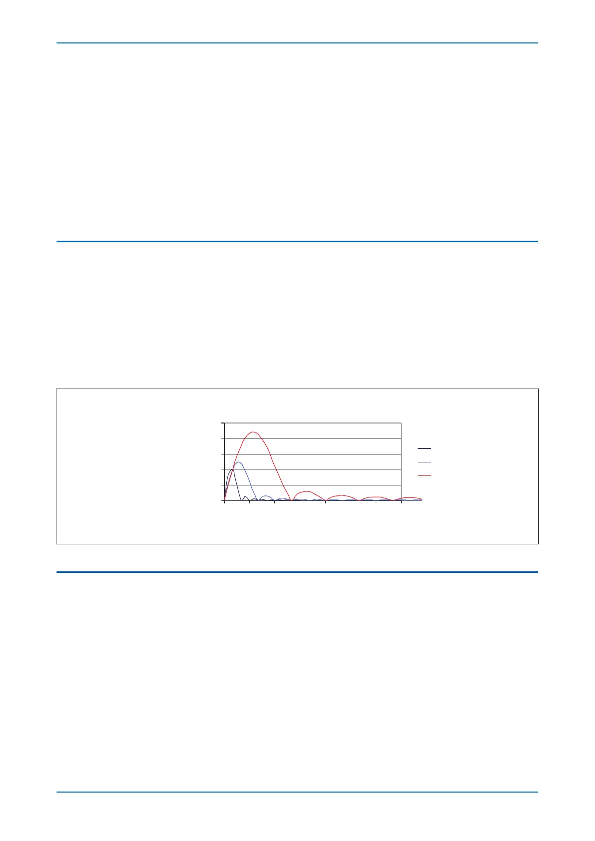
The following figure shows the frequency response of the 12, 24 and 48 coefficient filters, noting that all have a
gain of unity at the fundamental frequency:
E00308
Filter Response
Gain
Harmonic
Full
Quarter
Half
0 18
15
129
63
0.5
1
2
1.5
0
21
2.5
Figure 29: Frequency response of FIR filters
5.6
FOURIER SIGNAL PROCESSING
All backup protection and measurement functions use single-cycle fourier digital filtering to extract the power
frequency component. This filtering is performed on the main processor board.
When the protection and control task is re-started by the sampling function, it calculates the Fourier components
for the analog signals. Although some protection algorithms use some Fourier-derived harmonics (e.g. second
harmonic for magnetizing inrush), most protection functions are based on the Fourier-derived fundamental
components of the measured analog signals. The Fourier components of the input current and voltage signals are
stored in memory so that they can be accessed by all of the protection elements’ algorithms.
The Fourier components are calculated using single-cycle Fourier algorithm. This Fourier algorithm always uses
the most recent 48 samples from the 2-cycle buffer.
Most protection algorithms use the fundamental component. In this case, the Fourier algorithm extracts the power
frequency fundamental component from the signal to produce its magnitude and phase angle. This can be
represented in either polar format or rectangular format, depending on the functions and algorithms using it.
Chapter 4 - Software Design P543i/P545i
72 P54x1i-TM-EN-1

 Loading...


