9.4 SYSTEM CHECK PSL
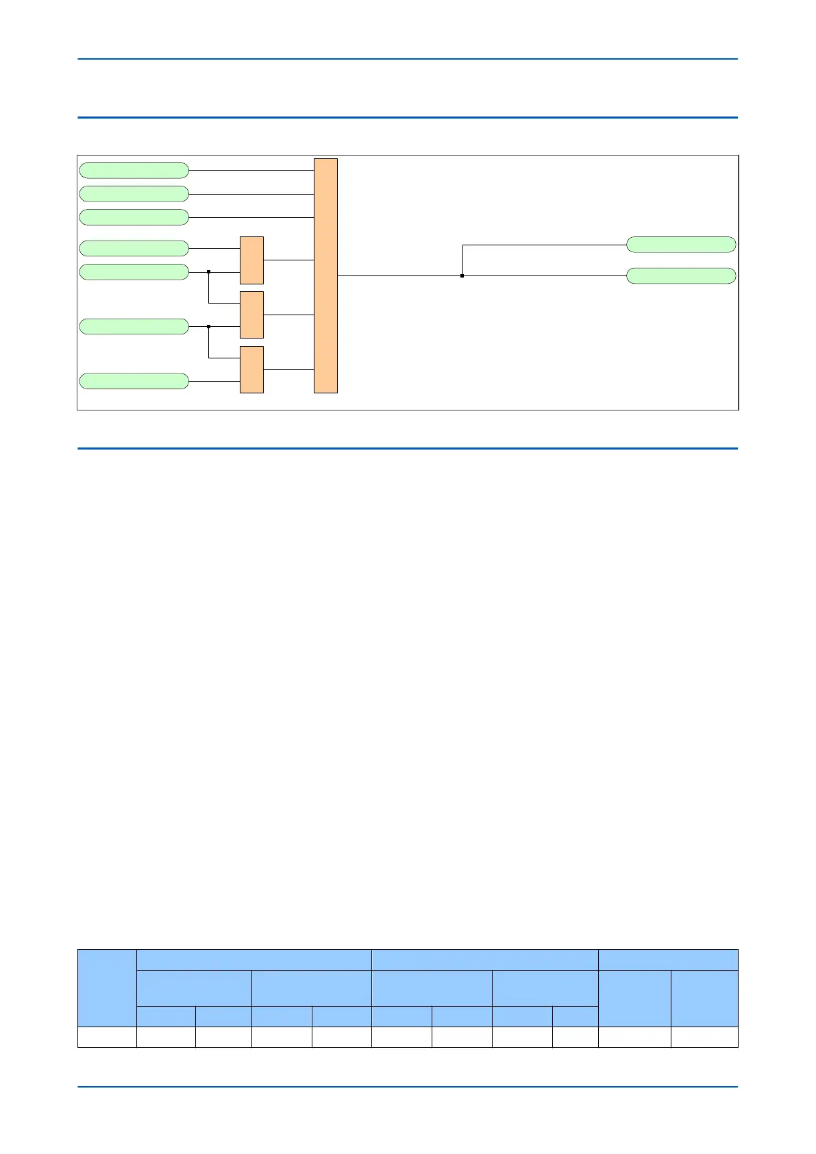
SysChks Inactive
V02028
Man Check Synch
AR Sys Checks
Check Sync 1 OK
Check Sync 2 OK
Live Line
Dead Bus
Dead Line
Live Bus
1
&
&
&
Figure 257: System Check PSL
9.5
APPLICATION NOTES
9.5.1 PREDICTIVE CLOSURE OF CIRCUIT BREAKER
The CS2 Adaptive setting compensates for the time taken to close the CB. When set to provide CB Close Time
compensation, a predictive approach is used to close the circuit breaker ensuring that closing occurs at close to 0º
therefore minimising the impact to the power system. The actual closing angle is subject to the constraints of the
existing product architecture, i.e. the protection task runs twice per power system cycle, based on frequency
tracking over the frequency range of 40 Hz to 70 Hz.
9.5.2
VOLTAGE AND PHASE ANGLE CORRECTION
For the Check Synchronisation function, the device needs to convert measured secondary voltages into primary
voltages. In some applications, VTs either side of the circuit breaker may have different VT Ratios. In such cases, a
magnitude correction factor is required.
There are some applications where the main VT is on the HV side of a transformer and the Check Sync VT is on the
LV side, or vice-versa. If the vector group of the transformer is not "0", the voltages are not in phase, so phase
correction is also necessary.
The correction factors are as follows and are located in the CT AND VT RATIOS column:
● C/S V kSM, where kSM is the voltage correction factor.
● C/S Phase kSA, where kSA is the angle correction factor.
Assuming C/S input setting is A-N, then:
The line and bus voltage magnitudes are matched if V
a sec
= V
cs sec
x C/S V kSA
The line and bus voltage angles are matched if ÐV
a sec
= ÐV
cs sec
+ C/S Phase kSA
The following application scenarios show where the voltage and angular correction factors are applied to match
different VT ratios:
Scenario
Physical Ratios (ph-N Values) Setting Ratios CS Correction Factors
Main VT Ratio CS VT Ratio
Main VT Ratio (ph-
ph) Always
CS VT Ratio
kSM kSA
Pri (kV) Sec (V) Pri (kV) Sec (V) Pri (kV) Sec (V) Pri (kV) Sec (V)
1 220/√3 110/√3 132/√3 100/√3 220 110 132 100 1.1 30º
Chapter 17 - Monitoring and Control P543i/P545i
456 P54x1i-TM-EN-1

 Loading...


