The CTS function is implemented in the SUPERVISION column of the relevant settings group, under the sub-heading
CT SUPERVISION.
The following settings are relevant for CT Supervision:
● CTS Status: to disable or enable CTS
● CTS VN< Inhibit: inhibits CTS if the zero sequence voltage exceeds this setting
● CTS IN> Set: determines the level of zero sequence current
● CTS Time Delay: determines the operating time delay
4.4
STANDARD CTS LOGIC
IN2
CTS IN> Set
VN
CTS VN< Inhibit
CTS Block
CT Fail Alarm
&
V01263
1
Inhibit CTS
Disable CTS
1
CTS Time Delay
Pickup
In indication mode , timer is set to 20ms
S
R
Q
&
1
&
CTS Status
Indication
Restrain
CTS Reset Mode
Manual
Auto
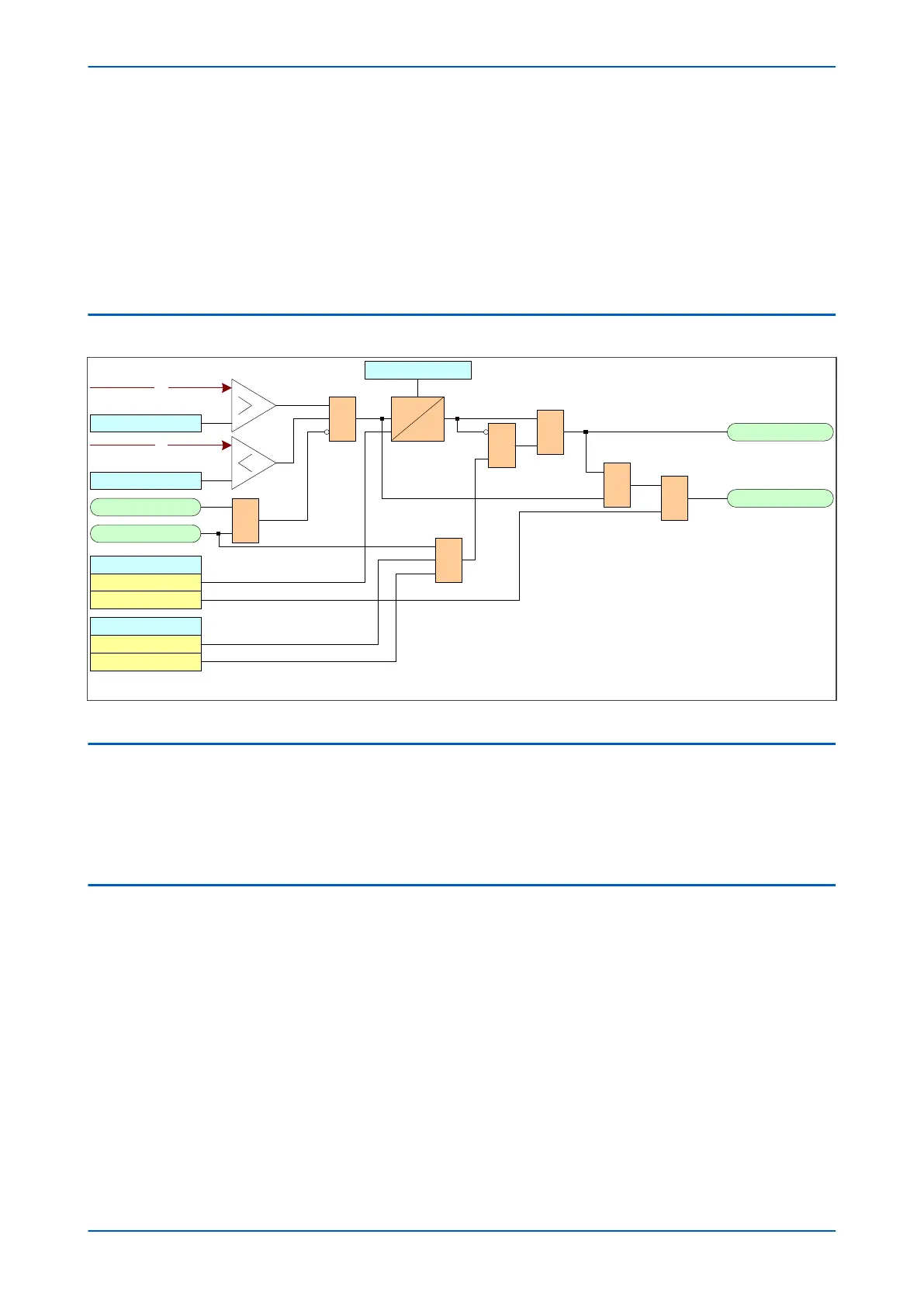
*
Figure 264: Standard CTS
4.5
CTS BLOCKING
Both the standard and differential CTS methods block protection elements operating from derived quantities, such
as Broken conductor, derived earth fault and negative sequence overcurrent. Measured quantities such as DEF
can be selectively blocked by designing an appropriate PSL scheme.
Differential CTS can be used to restrain the differential protection if required.
4.6
APPLICATION NOTES
4.6.1 SETTING GUIDELINES
The residual voltage setting, CTS VN< Inhibit and the residual current setting, CTS IN> Set, should be set to avoid
unwanted operation during healthy system conditions. For example:
● CTS VN< Inhibit should be set to 120% of the maximum steady state residual voltage.
● CTS IN> Set will typically be set below minimum load current.
● CTS Time Delay is generally set to 5 seconds.
Where the magnitude of residual voltage during an earth fault is unpredictable, the element can be disabled to
prevent protection elements being blocked during fault conditions.
P543i/P545i Chapter 18 - Supervision
P54x1i-TM-EN-1 477

 Loading...


