3.2 BASIC SCHEME SETTING
The Zone 1 time delay (tZ1) is generally set to zero, giving instantaneous operation.
The Zone 2 time delay (tZ2) is set to co-ordinate with Zone 1 fault clearance time for adjacent lines. The total fault
clearance time consists of the downstream Zone 1 operating time plus the associated breaker operating time.
Allowance must also be made for the Zone 2 elements to reset following clearance of an adjacent line fault and
also for a safety margin. A typical minimum Zone 2 time delay is of the order of 200 ms.
The Zone 3 time delay (tZ3) is typically set with the same considerations made for the Zone 2 time delay, except
that the delay needs to co-ordinate with the downstream Zone 2 fault clearance. A typical minimum Zone 3
operating time would be in the region of 400 ms.
The Zone 4 time delay (tZ4) needs to coordinate with any protection for adjacent lines in the protection’s reverse
direction.
Separate time delays can be applied to both phase and ground fault zones, for example where ground fault delays
are set longer to time grade with external ground/earth overcurrent protection.
Any zone (#) which may reach through a power transformer reactance, and measure secondary side faults within
that impedance zone should have a small time delay applied. This is to avoid tripping on the inrush current when
energizing the transformer.
As a general rule, if the Zone Reach setting is greater than 50% of the transformer reactance, set the Zone delay to
be 100 ms or greater. Alternatively, the 2nd harmonic detector output (which is available in the Programmable
Scheme Logic) may be used to block zones that may be at risk of tripping on inrush current. Settings for the inrush
detector are found in the SUPERVISION column.
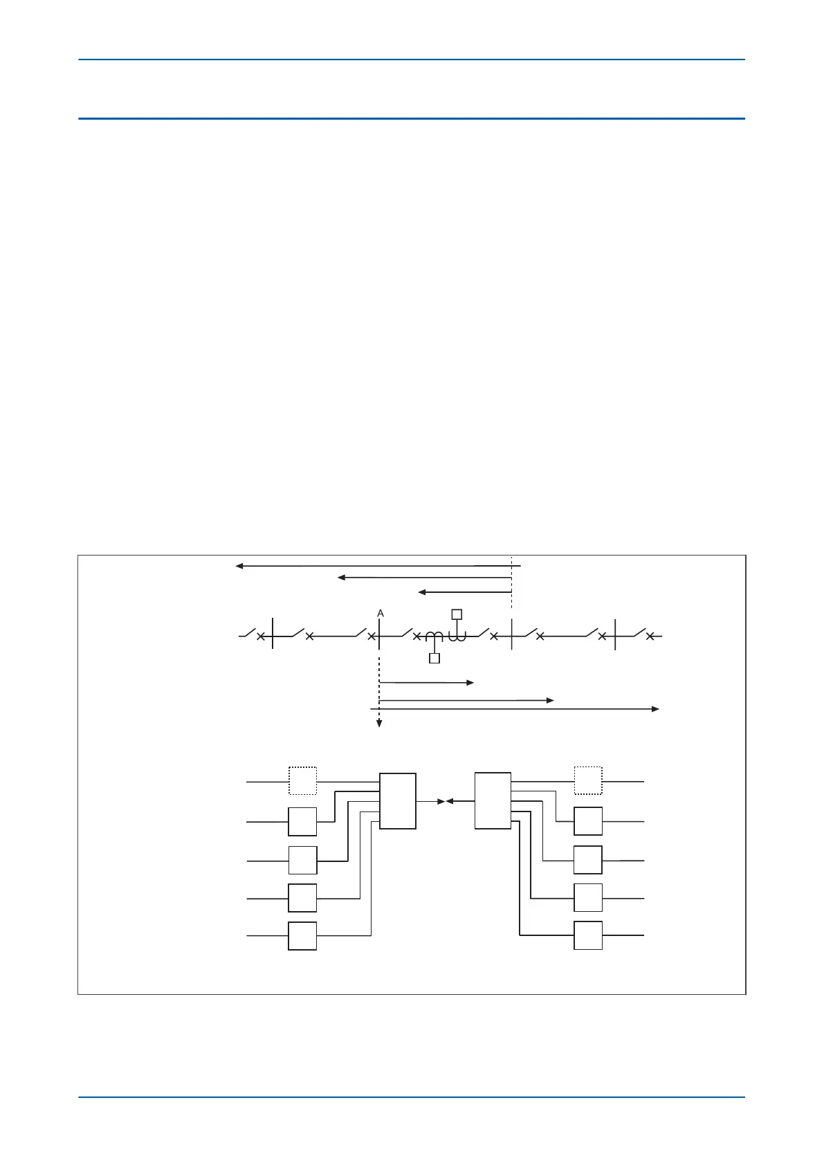
The figure below shows the typical application of the Basic scheme.
E02749
Zone 1
Zone 1
Zone 2
Zone 2
Zone 3
Zone 3
Relay A
Relay B
Typical application
Trip A
Trip B
Note: All timers can be set instantaneous
TZ4
TZ3
TZ2
TZP
TZ1
Z4
Z3
Z2
ZP
Z1
Z4
Z3
Z2
ZP
Z1
TZ4
TZ3
TZ2
TZP
TZ1
Z
Z
B
1
1
Figure 137: Basic time stepped distance scheme
Chapter 9 - Non-Aided Schemes P543i/P545i
258 P54x1i-TM-EN-1

 Loading...


