2 INTRODUCTION
Amongst protection engineers, the basic principles of Distance Protection are widely documented and understood.
If you are reading this chapter, we assume that you are familiar with the principles of distance protection and
associated components such as Aided Schemes. However, to help you choose suitable settings, some of the
principles of operation of the Distance Measuring Zones is included in this chapter.
2.1
DISTANCE PROTECTION PRINCIPLE
The principle behind Distance protection is based on using measured values of voltage and current to calculate
impedance seen from a relaying point. If the impedance calculated is an unexpected value, this may indicate a
fault.
The impedance of a transmission line is proportional to its length. If voltage and current signals are available at a
relaying point, they can be used to calculate the impedance value seen from the relaying point. Impedance values
looking forward into the line, as well as values looking in the reverse direction behind the relaying point can be
calculated. The calculated impedance is compared with so called 'Reach Points'. Reach Points are impedance
values, which are used to define zones of protection. The device contains settings by which you can configure
these Reach Points. The zones are usually numbered (for example: Zone 1, Zone 2, Zone 3). By comparing the
calculated impedance with the zone reach points, the device can determine whether a fault is present and if
necessary, trip the associated circuit breakers.
2.2
PERFORMANCE INFLUENCING FACTORS
As well as the accuracy of the signals presented by the input transducers, an important factor that influences the
performance of distance protection is the relationship between the source and line impedance. This is the System
Impedance Ratio (SIR), and is defined by Z
S
/Z
L
.
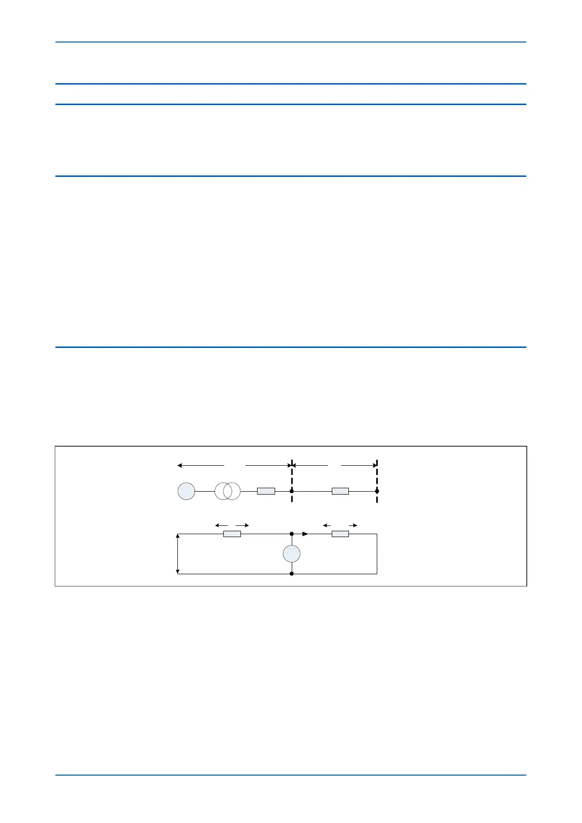
The following figure represents a fault condition on an electrical power system, and can be used to demonstrate
the relationship.
V02753
~
Source
R
Line
V
V
S
V
L
=V
R
Z
L
I
R
VR
Figure 50: System Impedance Ratio
The voltage V applied to the impedance loop is the open circuit voltage of the power system. Point R represents the
protection location; I
R
and V
R
are the current and voltage measured by the relay, respectively.
The impedances Z
s
and Z
L
are described as source and line impedances because of their position with respect to
the protection location. Source impedance Z
s
is a measure of the fault level at the relaying point. For faults
involving earth it is dependent on the method of system earthing behind the relaying point. Line impedance Z
L
is a
measure of the impedance of the protected section. The voltage V
R
applied to the relay is, therefore, I
R
Z
L
. For a
fault at the reach point, this may be expressed in terms of the System Impedeance Ratio, using the following
expression:
V
R
= V/(SIR+1)
Chapter 7 - Distance Protection P543i/P545i
136 P54x1i-TM-EN-1

 Loading...


