13 APPLICATION NOTES
13.1 SETTING UP THE PHASE DIFFERENTIAL CHARACTERISTIC
The biased phase current differential characteristic is defined by four protection settings. Each can be set
independently. This flexibility allows the characteristic to be set for particular sensitivity and current transformer
requirements. To simplify setting the protection, however, we strongly recommend three of the settings be fixed as:
● Phase Is2 = 2.0 pu
● Phase k1 = 30% (This provides stability for small CT mismatches, while ensuring good sensitivity to resistive
faults under heavy load conditions
● Phase k2 = 150% (For 2 terminal applications to provides stability under heavy through fault current
conditions)
● Phase k2 = 100% (For 3 terminal applications to provides stability under heavy through fault current
conditions)
These settings give a characteristic suitable for most applications so that only the Phase Is1 setting needs
changing from the default value.
Phase Is1 is the setting which determines the minimum pick-up of the phase current differential elements. This
value should be set to account for any mismatch between the current transformers at the different terminals, as
well the capacitive charging current if this is not compensated.
If voltage inputs are connected, the charging current can be compensated for. To do this you need to set the
Compensation setting in the CURRENT DIFF column to Cap Charging and then programme the line positive
sequence capacitive susceptance value into the Susceptance setting now apparent in the CURRENT DIFF column.
If Cap Charging is selected, Phase Is1 may be set below the value of line charging current. We recommend that
you choose Phase Is1 only sufficiently below the charging current to offer the required fault resistance coverage
as now described.
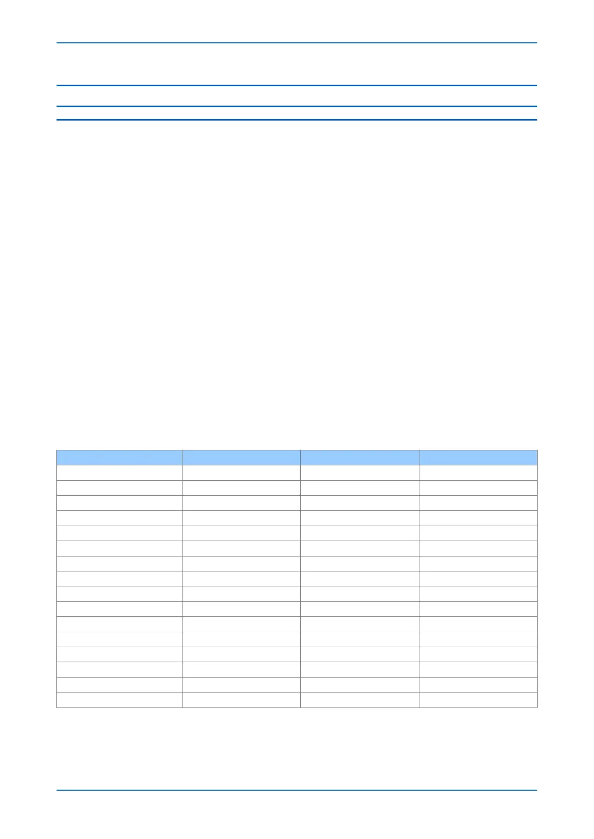
The table below shows some typical steady state charging currents for various lines and cables.
Voltage (kV) Core formation and spacing Conductor size in mm2 Charging current A/km
11 kV Cable Three-core 120 1.2
33 kV Cable Three-core 120 1.8
33 kV Cable Close-trefoil 300 2.5
66 kV Cable Flat, 127 mm 630 10
132 kV Overhead Line 175 0.22
132 kV Overhead Line 400 0.44
132 kV Cable Three-core 500 10
132 kV Cable Flat, 520 mm 600 20
275 kV Overhead Line 2 x 175 0.58
275 kV Overhead Line 2 x 400 0.58
275 kV Cable Flat, 205 mm 1150 19
275 kV Cable Flat, 260 mm 2000 24
400 kV Overhead Line 2 x 400 0.85
400 kV Overhead Line 4 x 400 0.98
400 kV Cable Flat, 145 mm 2000 28
400 kV Cable Tref., 585 mm 3000 33
If capacitive charging current compensation is not used, the setting of Phase Is1 must be set above 2.5 times the
steady state charging current. Where charging current is low or negligible, the recommended setting of 0.2 pu
(factory default) should be applied.
P543i/P545i Chapter 6 - Current Differential Protection
P54x1i-TM-EN-1 125

 Loading...


