The Fourier function acts as a filter, with zero gain at DC and unity gain at the fundamental, but with good
harmonic rejection for all harmonic frequencies up to the nyquist frequency. Frequencies beyond this nyquist
frequency are known as alias frequencies, which are introduced when the sampling frequency becomes less than
twice the frequency component being sampled. However, the Alias frequencies are significantly attenuated by an
anti-aliasing filter (low pass filter), which acts on the analog signals before they are sampled. The ideal cut-off point
of an anti-aliasing low pass filter would be set at:
(samples per cycle)
´
(fundamental frequency)/2
At 48samples per cycle, this would be nominally 1200 Hz for a 50 Hz system, or 1440 Hz for a 60 Hz system.
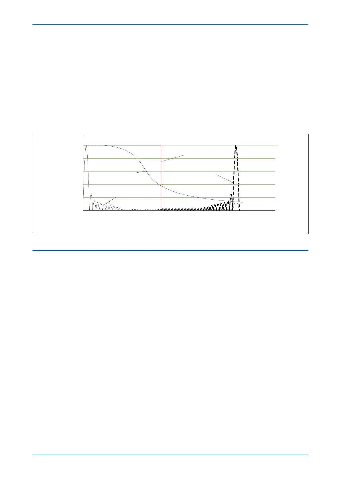
The following figure shows the nominal frequency response of the anti-alias filter and the Fourier filter for a 48-
sample single cycle fourier algorithm acting on the fundamental component:
Ideal anti-alias filter response
Real anti-alias filter
response
2 3...
1
0.2
0.4
0.6
0.8
241
50 Hz 1200 Hz 2400 Hz
V00306
Fourier Response
without anti -alias filter
Fourier Response
with anti-alias filter
Alias frequency
Figure 30: Frequency Response (indicative only)
5.7
PROGRAMMABLE SCHEME LOGIC
The purpose of the programmable scheme logic (PSL) is to allow you to configure your own protection schemes to
suit your particular application. This is done with programmable logic gates and delay timers. To allow greater
flexibility, different PSL is allowed for each of the four setting groups.
The input to the PSL is any combination of the status of the digital input signals from the opto-isolators on the
input board, the outputs of the protection elements such as protection starts and trips, and the outputs of the fixed
protection scheme logic (FSL). The fixed scheme logic provides the standard protection schemes. The PSL consists
of software logic gates and timers. The logic gates can be programmed to perform a range of different logic
functions and can accept any number of inputs. The timers are used either to create a programmable delay,
and/or to condition the logic outputs, such as to create a pulse of fixed duration on the output regardless of the
length of the pulse on the input. The outputs of the PSL are the LEDs on the front panel of the relay and the output
contacts at the rear.
The execution of the PSL logic is event driven. The logic is processed whenever any of its inputs change, for
example as a result of a change in one of the digital input signals or a trip output from a protection element. Also,
only the part of the PSL logic that is affected by the particular input change that has occurred is processed. This
reduces the amount of processing time that is used by the PSL. The protection & control software updates the logic
delay timers and checks for a change in the PSL input signals every time it runs.
The PSL can be configured to create very complex schemes. Because of this PSL desing is achieved by means of a
PC support package called the PSL Editor. This is available as part of the settings application software MiCOm S1
Agile, or as a standalone software module.
P543i/P545i Chapter 4 - Software Design
P54x1i-TM-EN-1 73

 Loading...


