7.11 DISTANCE PROTECTION WORKED EXAMPLE
This section presents a worked example of how to set the Distance protection. For this case study, we assume that
Zone 1 Extension is not used, and that only three zones are required for basic Distance protection (Zones 1 and 2
Forward Directional, and Zone 3 Forward Offset). The following settings are derived:
● Line Impedance
● Residual Compensation
● Zone 1 reach settings for phase-faults and earth-faults
● Zone 2 reach settings for phase-faults and earth-faults
● Zone 3 reach settings for phase-faults and earth-faults
● Zone 3 reverse reach settings
● Zone 4 reach settings (for use with Permissive Overreach or Blocking schemes if needed)
● Load avoidance
The settings are applicable whether the Distance protection characteristics are set to Mho, or Quadrilateral. If you
choose Quadrilateral however, you will need to consider the Resistive reaches of Quadrilaterals.
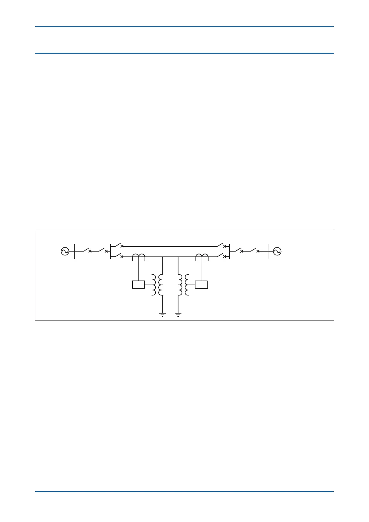
For this study, we wish to protect one line of a double 230kV, 100km line between a substation at Green Valley and
a substation at Blue river. There are generating sources at Tiger Bay, 80 km from Green Valley and at Rocky Bay, 60
km from Blue River.
The single-line diagram for the system is shown in the following figure:
Tiger Bay
Green Valley Blue River
Rocky Bay
80 km
100 km
60 km
IED IED
E02705
Figure 99: Example power system
The system data is as follows:
● System Voltage: 230kV
● System earthing: Solid
● CT ratio: 1200 : 5
● VT ratio: 230 000 : 115
● Line length: 100km
●
Positive sequence line impedance (Z1): 0.089 + j0.476 ohms/km = 0.484Ð79.4°
●
Zero sequence line impedance (Z0): 0.426 + j1.576 ohms/km = 1.632Ð74.8°
●
Z0/Z1: 3.372Ð4.6°
● Green Valley substation fault level: 2000 MVA to 5000 MVA
● Blue river substation fault level: 1000 MVA to 3000 MVA
● Circuit continuous rating: 400 MVA
● Worst case power factor of load: 0.85
P543i/P545i Chapter 7 - Distance Protection
P54x1i-TM-EN-1 201

 Loading...


