4.7 AIDED DISTANCE LOGIC DIAGRAMS
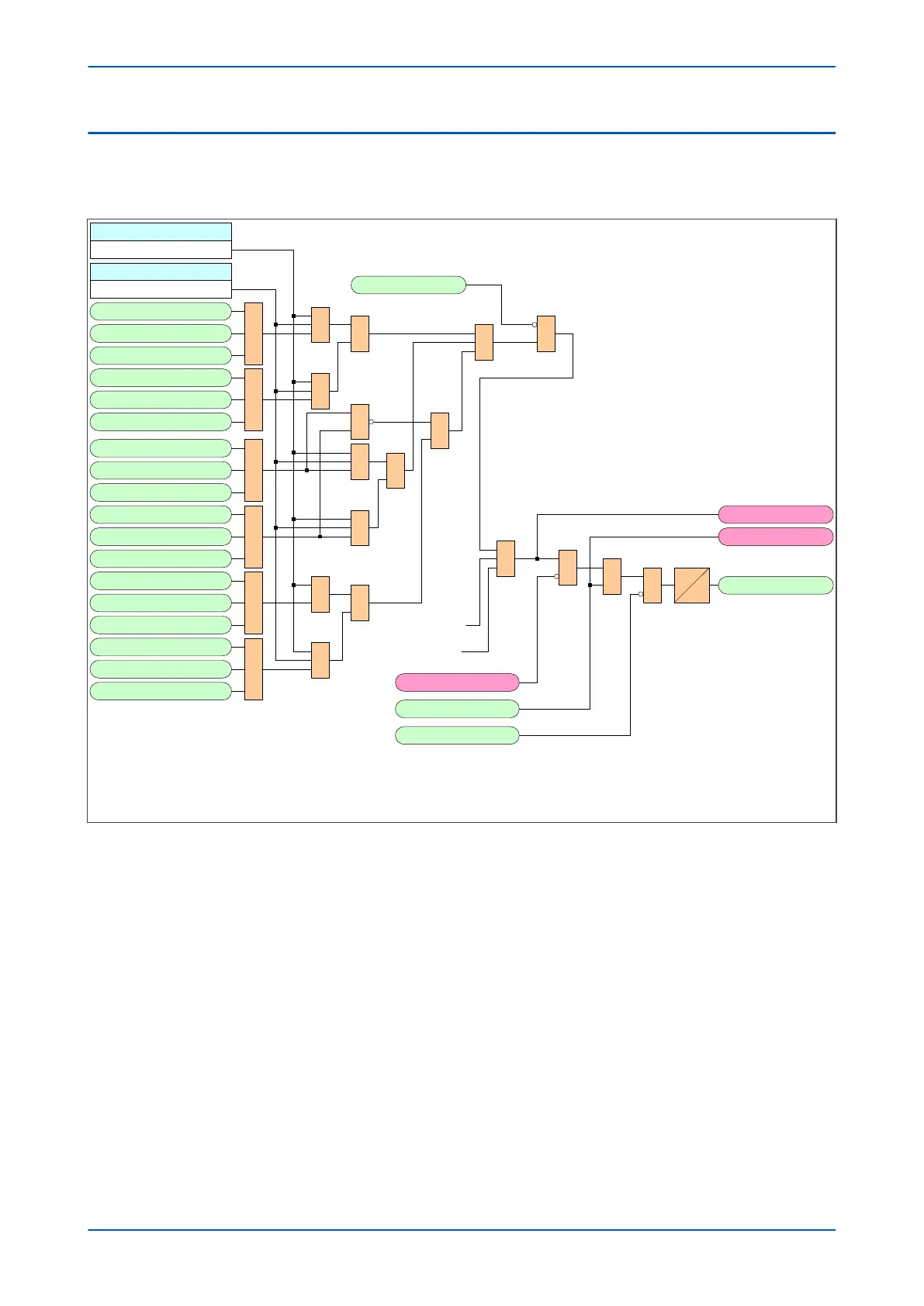
4.7.1 AIDED DISTANCE SEND LOGIC
V03505
Aid 1 Distance
Scheme options *
Custom Send Mask
Masking options *
&
1
Zone1 AN Element
Zone1 BN Element
Zone1 CN Element
1
Zone1 AB Element
Zone1 BC Element
Zone1 CA Element
1
Zone2 AN Element
Zone2 BN Element
Zone2 CN Element
1
Zone2 AB Element
Zone2 BC Element
Zone2 CA Element
1
Zone4 AN Element
Zone4 BN Element
Zone4 CN Element
1
Zone4 AB Element
Zone4 BC Element
Zone4 CA Element
&
&
&
&
&
1
1
1
&
1
&
1
Aid1 InhibitDist
Aided 1 Send
t
RG
&
1
Aid1 Block Send
Signal Send
Blk Send
&
Echo Send
Aid1 Custom Send
1
From Aided 1 DEF
From Aided 1 Delta
(if applicable)
Notes:
This example assumes zone 2 distance phase and distance ground
elements are enabled .
Aided 1 scheme only shown.
Note: For the purpose of clarity , this diagram shows the first
relevant stage number for each signal and setting name .
960
961
962
963
964
965
966
967
968
969
970
971
984
985
986
987
988
989
394
498
497
496
Figure 106: Aided Distance Send logic
Chapter 8 - Carrier Aided Schemes P543i/P545i
222 P54x1i-TM-EN-1

 Loading...


