P54x
V02621
P54x
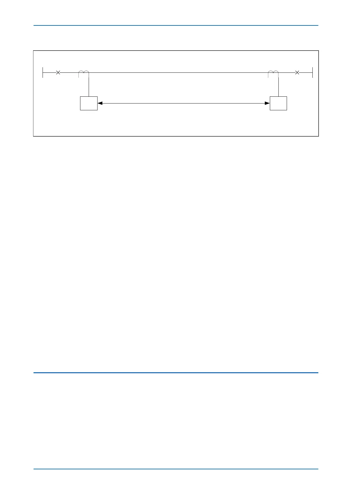
Steady state charging current
= 2.5 A/km – cable
= 0.1 A/km – overhead line
Digital communication link
Protected line
33 kV 33 kV
400/1400/1
25 km
Figure 48: Typical two-terminal plain feeder circuit
In the case that voltage inputs are not in place, no facility to account for line charging current is available. The
setting of Phase Is1 must therefore be set above 2.5 times the steady state charging current value. In this example,
assume a cable is used and there are not VT inputs connected to the device:
Phase Is1 > 2.5(Ich)
Phase Is1 > 2.5 (25 km x 2.5 A/km)
Phase Is1 > 156.25 A
The line CTs are rated at 400 amps primary. The setting of Phase Is1 must therefore exceed 156.25/400 = 0.391 pu.
Therefore select:
Phase Is1 = 0.4 pu
If VTs are connected, a facility exists to overcome the effects of the line charging current. To use this you need to
set the Compensation setting in the CURRENT DIFF column to Cap Charging and then programme the line
positive sequence capacitive susceptance value into the Susceptance setting now apparent in the CURRENT DIFF
column. This can be calculated from the line charging current as follows (assuming a VT ratio of 33 kV / 110 V):
Ich = 25 x 2.5 A = 62.5 A
Susceptance B =
w
C = Ich/V
B = 62.5 A/(33/
Ö
3 ) kV primary
B = 3.28 x 10⁻³ S primary
Therefore set:
B = 3.28 mS primary (= 2.46 mS secondary)
Phase Is1 may now be set below the value of line charging current if required, however we suggest that you
choose Phase Is1 only sufficiently below the charging current to offer the required fault resistance coverage.
Where charging current is low or negligible, the recommended factory default setting of 0.2xIn should be applied.
13.7
SETTING A THREE-TERMINAL PHASE CURRENT DIFFERENTIAL ELEMENT
All four settings are user adjustable. This flexibility in settings allows the phase current differential characteristic to
be tailored to suit particular sensitivity and CT requirements. To simplify your task, we strongly recommend three of
the settings be fixed to:
Phase Is2 = 2.0 pu
Phase k1 = 30%
Phase k2 = 100%
P543i/P545i Chapter 6 - Current Differential Protection
P54x1i-TM-EN-1 129

 Loading...


