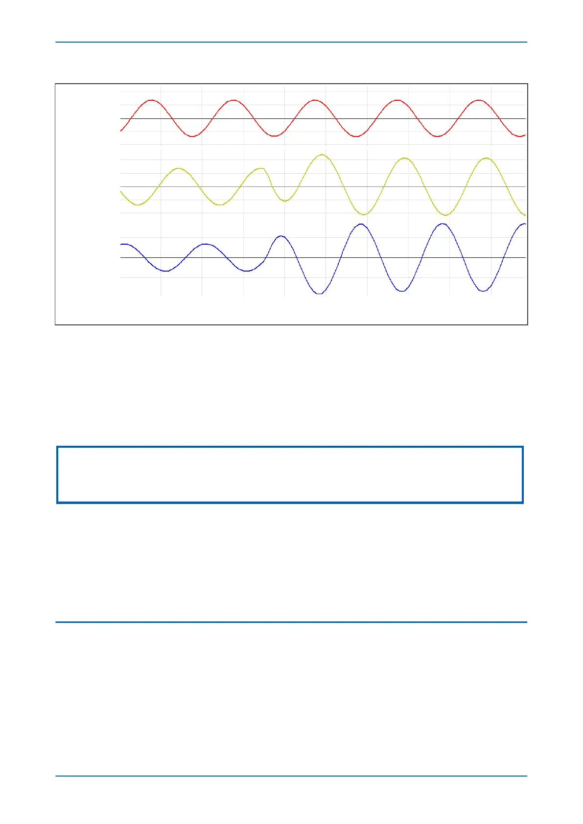
Figure 77: Phase to phase current changes for C phase-to-ground (CN) fault
As default, phase selection is made when any superimposed current exceeds 5% of nominal current (0.05 In).
Any superimposed current greater than 80% of the largest superimposed current is included in the phase selection
logic.
For applications which might experience high levels of sub-synchronous currents, the phase selector automatically
raises the threshold from the default 5% of In, in order to prevent sporadic operation whilst maintaining high
sensitivity to faults.
Note:
If you test the distance elements using test sets, which do not provide a dynamic model to generate true fault delta
conditions, you need to set Static Test Mode to Enabled in the COMMISSION TESTS column. This disables phase selector
control and forces the distance protection to use a conventional (non-delta) directional line.
The phase selector picks up on fault detection, and enables Distance protection on all elements which have been
selected by the pick-up. These elements are enabled for 2 cycles, and normally this will result in tripping. On double
ground-to-phase faults, only appropriate phase elements are enabled. This is because they are generally more
accurate than ground elements under these conditions. If, however, tripping is not initiated within the 2 cycles, for
the following 5 cycles all Distance elements (including all phase-earth elements) are enabled. During these five
cycles, this could lead to incorrect operation of earth-fault elements in case of an out-of-zone double-phase-earth
fault. This is because one of the phase-earth elements could demonstrate significant overreach, which may result
in maloperation. To help prevent this, a Biased Neutral Current Detector is incorporated.
4.5
BIASED NEUTRAL CURRENT DETECTOR
The Biased Neutral Current Detector permits the earth-fault elements to operate only if sufficient neutral current is
detected. The Biased Neutral Current Detector characteristic is illustrated in the following figure.
Chapter 7 - Distance Protection P543i/P545i
170 P54x1i-TM-EN-1

 Loading...


