2.1.2 UNDERFREQUENCY PROTECTION LOGIC
F<1 TripF<1 Trip
F<1 StatusF<1 Status
V00861
FreqFreq
DT
F<1 StartF<1 Start
&
EnabledEnabled
F<1 SettingF<1 Setting
Freq Not FoundFreq Not Found
AveragingAveraging
F<1 Timer BlockF<1 Timer Block
All Poles DeadAll Poles Dead
1
890
1370
1149
1155
1161
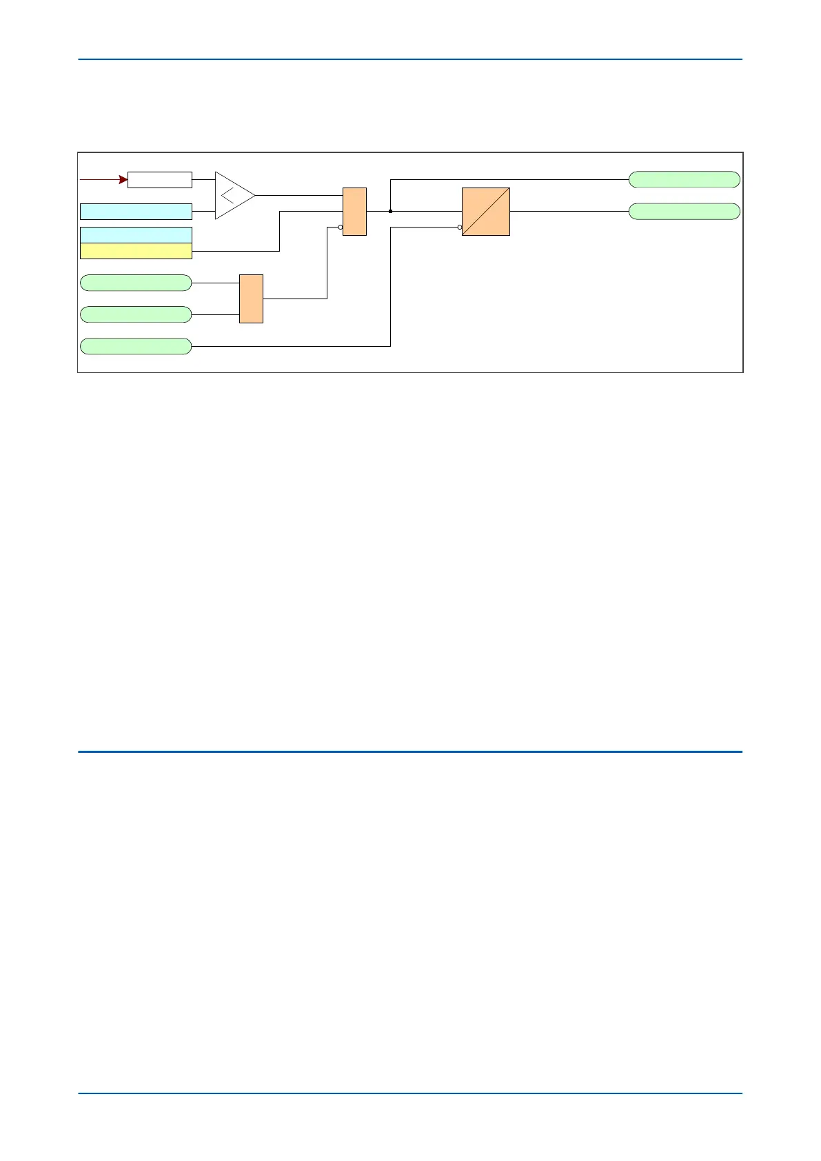
Figure 237: Underfrequency logic (single stage)
If the frequency is below the setting and not blocked the DT timer is started. If the frequency cannot be
determined, the function is blocked.
2.1.3
APPLICATION NOTES
2.1.3.1 SETTING GUIDELINES
In order to minimise the effects of underfrequency, a multi-stage load shedding scheme may be used with the
plant loads prioritised and grouped. During an underfrequency condition, the load groups are disconnected
sequentially, with the highest priority group being the last one to be disconnected.
The effectiveness of each load shedding stage depends on the proportion of power deficiency it represents. If the
load shedding stage is too small compared with the prevailing generation deficiency, then there may be no
improvement in the frequency. This should be taken into account when forming the load groups.
Time delays should be sufficient to override any transient dips in frequency, as well as to provide time for the
frequency controls in the system to respond. These should not be excessive as this could jeopardize system
stability. Time delay settings of 5 - 20 s are typical.
The protection function should be set so that declared frequency-time limits for the generating set are not
infringed. Typically, a 10% underfrequency condition should be continuously sustainable.
2.2
OVERFREQUENCY PROTECTION
An increased system frequency arises when the mechanical power input to a generator exceeds the electrical
power output. This could happen, for instance, when there is a sudden loss of load due to tripping of an outgoing
feeder from the plant to a load centre. Under such conditions, the governor would normally respond quickly to
obtain a balance between the mechanical input and electrical output, thereby restoring normal frequency.
Overfrequency protection is required as a backup to cater for cases where the reaction of the control equipment is
too slow.
2.2.1
OVERFREQUENCY PROTECTION IMPLEMENTATION
Simple overfrequency Protection is configured in the FREQ PROTECTION column of the relevant settings group.
The device provides 2 stages of overfrequency protection. The function uses the following settings (shown for
stage 1 only - other stages follow the same principles).
● F>1 Status: enables or disables underfrequency protection for the relevant stage
● F>1 Setting: defines the frequency pickup setting
● F>1 Time Delay: sets the time delay
P543i/P545i Chapter 15 - Frequency Protection Functions
P54x1i-TM-EN-1 413

 Loading...


