ta
tB1
tB2
tA1
tA2
tB3*
tA3
tA4
tA5
tA*
tA6
Relay A
tp 2
tp 1
tB3
tB4
tB5
tB6
Relay B
tB*
tc
td
E02607
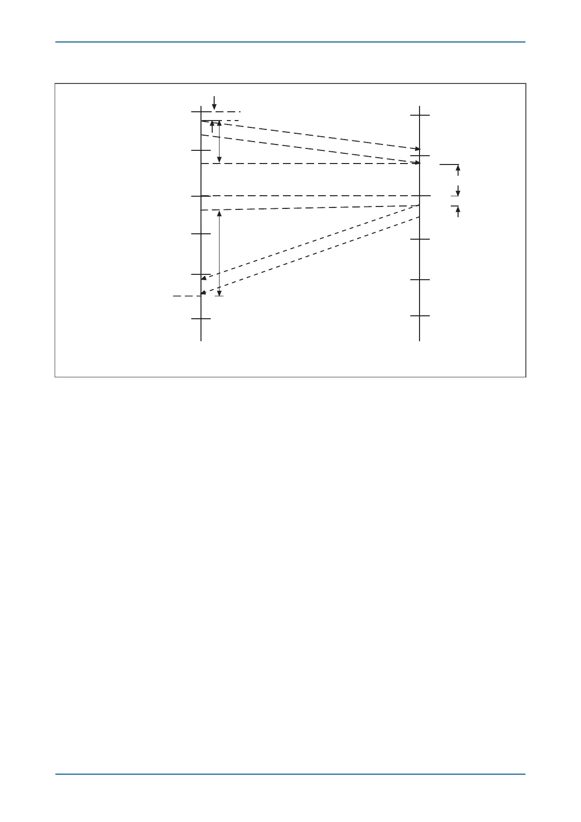
Figure 35: Asymmetric propogation delay times
The GPS synchronised values at terminal A (tA1, etc.) can be individually compared with those at terminal B (tB1,
etc.) to derive the bias and differential currents. The propagation delay times are not required for the derivation of
the bias and differential currents, but they can be calculated individually as tp1, and tp2, and they are stored for
potential use if GPS synchronisation fails.
Chapter 6 - Current Differential Protection P543i/P545i
104 P54x1i-TM-EN-1

 Loading...


