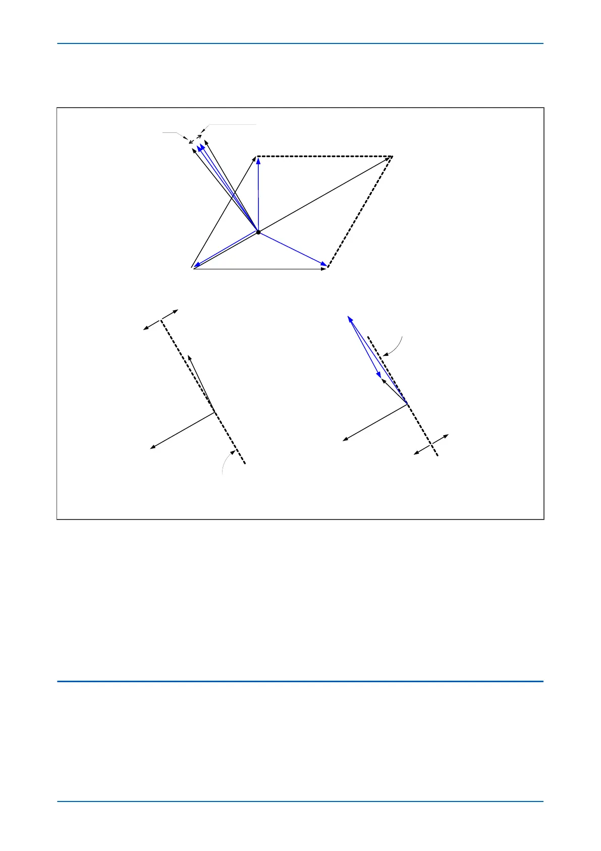
In practical cases, however, resistance is present, resulting in the following phasor diagrams:
V00641
a) capacitive and inductive currents with resistive components
N
b) Unfaulted line
c) Faulted line
Operate
Restrain
Zero torque line for 0° RCA
Zero torque line for 0° RCA
Operate
Restrain
I’
L
Resistive component
in grounding coil
Resistive component
in feeder
(IAH1 + IH2 + IH3)’
3V
0
BC
A
-I
H 1
- I
H2
I
L
IR1 = IH1
IR 3
I
R3
= I
F
+ I
H3
= I
L
- I
H1
- I
H12
V
res
= -3V
0
V
res
= -3V
0
Figure 87: Phase C earth fault in Petersen Coil earthed system: practical case with resistance present
If the residual voltage is used as the polarising voltage, the residual current is phase shifted by an angle less than
90° on the faulted feeder, and greater than 90° on the healthy feeders. With an RCA of 0°, the healthy feeder
residual current will fall in the ‘restrain’ area of the characteristic while the faulted feeder residual current falls in
the ‘operate’ area.
Often, a resistance is deliberately inserted in parallel with the Petersen Coil to ensure a measurable earth fault
current and increase the angular difference between the residual signals to reinforce the directional decision.
Directionality is usually implemented using a Wattmetric function, or a transient earth fault detection function
(TEFD), rather than a simple directional function, since they are more sensitive. For further information about TEFD,
refer to Transient Earth Fault Detection in the Current Protection Functions chapter.
6.2
EARTH FAULT DISTANCE PROTECTION FOR ISOLATED AND COMPENSATED
SYSTEMS
There are four types of fault that need to be considered when providing distance protection for isolated or
compensation earthed systems. These are faults involving three phases, phase to phase faults, faults involving just
a single-phase to earth, and cross-country faults involving separate single phase to earth faults.
Chapter 7 - Distance Protection P543i/P545i
182 P54x1i-TM-EN-1

 Loading...


