V02721
Tripping
Region
R
jX
R’
-jX
Impedance Reach line
Reverse Impedance Reach line
Resistive
Reach line
Reverse Resistive
Reach line
Z
Z’
θ
+R
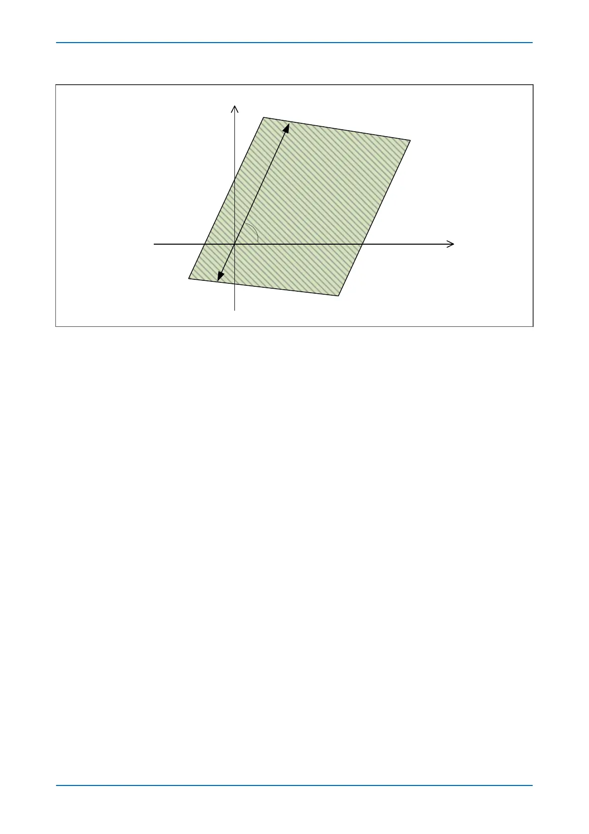
Figure 61: General Quadrilateral Characteristic Limits
In the figure, an Offset Quadrilateral characteristic is defined by its Impedance Reach, Z, (and Reverse Impedance
Reach, Z’), its Resistive Reach, R, (and Reverse Resistive Reach, R’), and the zone angle (θ).
The two near-horizontal lines (Impedance Reach Line and Reverse Impedance Reach Line) set the reactive
impedance limits of the tripping zone. The two near-vertical lines (Resistive Reach Line and Reverse Resistive
Reach Line) set the resistive impedance limits.
The Resistive Reach Lines (also called Resistive Blinders) are parallel and set at the angle of the zone’s
characteristic impedance.
The Impedance Reach Lines exhibit a characteristic tilt (slope). A line that tilts to reduce the reactive reach
(negative tilt/tilt down) encourages underreaching; A line that tilts to increase the reactive reach (positive tilt/tilt up)
encourages overreaching. The tilt can be used to reinforce the overreaching/underreaching requirements of the
zone. For example, for an underreaching Forward zone, a negative tilt will ensure that the measurement continues
to underreach, even with increasing fault resistance.
The Impedance Reach, Z, and the Resistive Reach, R, apply in the context of the direction of the protection. For a
Forward Zone, or an Offset Zone, Z and R look into the protected plant. For a Reverse Zone, Z and R look behind the
protected plant. Reactive Line tilts follow the same convention.
3.2.1
DIRECTIONAL QUADRILATERALS
A Directional Line overlaid onto an Offset characteristic is used to create a Directional one as shown in the
following figure:
Chapter 7 - Distance Protection P543i/P545i
150 P54x1i-TM-EN-1

 Loading...


