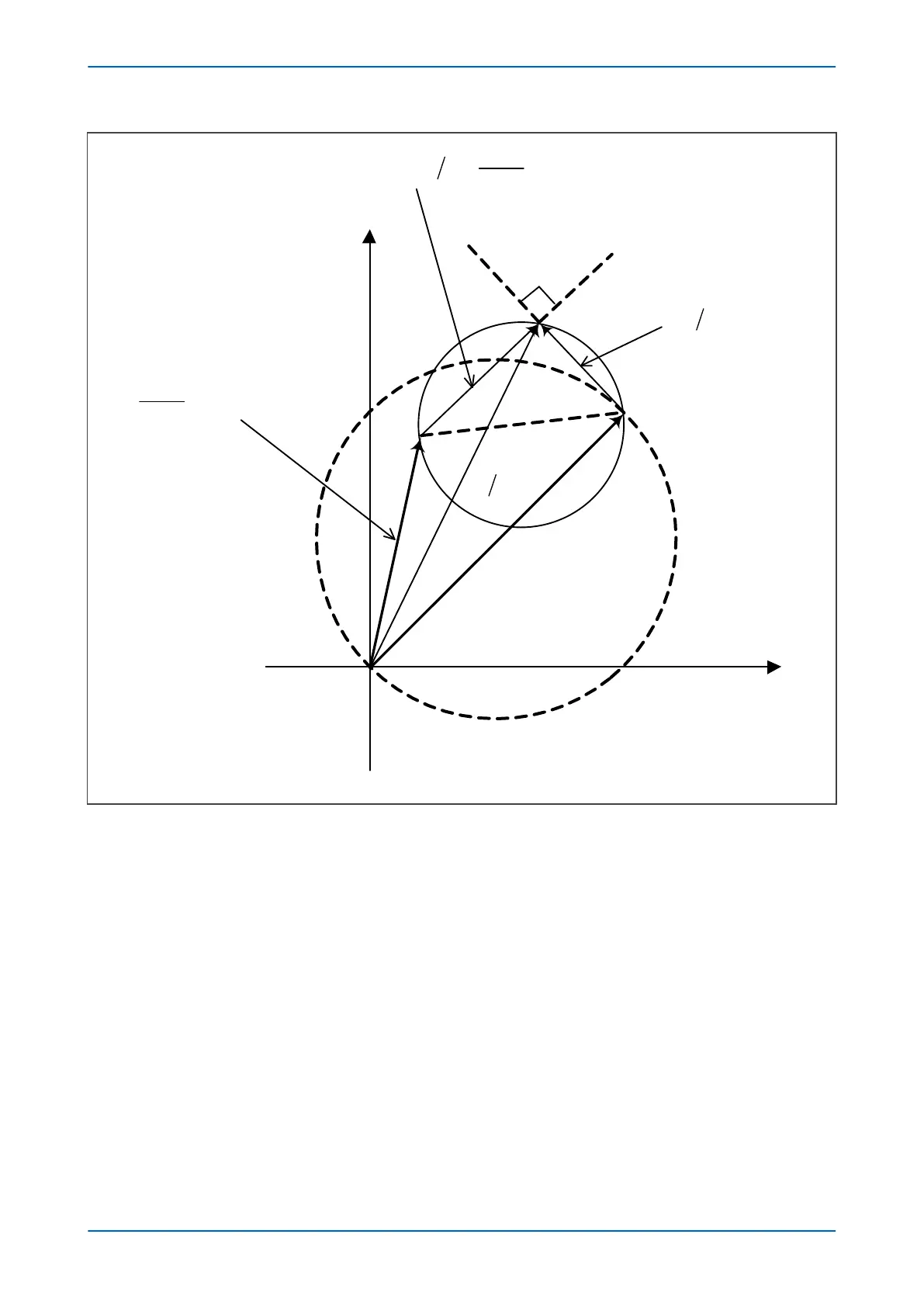
Figure 59: Mho contraction – reverse fault
The Mho contraction associated with reverse faults is as follows:
Mho Contraction = (Z
S
+ Z
L
).p/(1 + p)
where Z
S
+ Z
L
is the impedance of the line and the source ahead of the relaying point.
Using the source and line impedances is a simple way of representing the Mho contraction. The protection does
not calculate Z
S
+ Z
L
internally, it only deals with the signals S
1
and S
2
provided to the Mho comparators. In some
cases the source and line impedances are different from their actual values used in various power system studies.
This is mainly due to pre-fault current and the residual compensation for phase-to-ground loops. To plot an
accurate impedance characteristic, calculate the values of Z
S
+ Z
L
as follows:
Z
S
+ Z
L
= (V - V
mem
)/I
3.1.7
CROSS POLARIZATION OF MHO CHARACTERISTICS
If the voltage collapses on a faulted phase, it may be possible to use healthy phase voltage components to derive
a polarizing signal to make the directional decision. This process is called cross-polarization.
P543i/P545i Chapter 7 - Distance Protection
P54x1i-TM-EN-1 147

 Loading...


