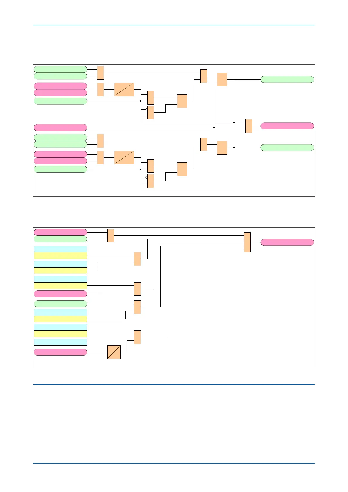
5.13.3 SUCCESFUL AUTORECLOSE SIGNALS LOGIC DIAGRAM
V03358
&
3P Reclaim TComp
R
Q
S
SETCB1SPCL
1P Reclaim TComp
CB Closed 3 Ph
CB1OP1 P
RESCB1ARSUCC
1
RD
Q
S
CB Succ 1P AR
1 CB1ARSUCC
&
0.02S
0
&
1
CB Succ 3P AR
&
3P Reclaim TComp
R
Q
S
SETCB13 PCL
1P Reclaim TComp
CB Closed 3 Ph
CB1OP2/ 3P
1
RD
Q
S
&
0.02S
0
&
1
Figure 194: Successful Autoreclose Signals logic diagram (Module 36)
5.13.4
AUTORECLOSE RESET SUCCESSFUL INDICATION LOGIC DIAGRAM
V03361
AROK Reset Time
CB1 ARSUCC
1
CB1 OPANY
AR Start
Res AROK by UI
Enabled
Res AROK by NoAR
Enabled
Res AROK by TDly
Enabled
Reset AROK Ind
Yes
1 RESCB1 ARSUCC
AR DISABLED
&
&
&
&
0
t
Res AROK by Ext
Enabled
Ext Rst AROK
Figure 195: Autoreclose Reset Successful Indication logic diagram (Module 37)
5.14
CB HEALTHY AND SYSTEM CHECK TIMERS
This logic provides signals to cancel Autoreclose if the circuit breaker is not healthy (for example low gas pressure)
or system check conditions are not satisfied (for example required line & bus voltage conditions) when the scheme
is ready to close the circuit breaker.
At the completion of a dead time, the logic starts an Autoreclose healthy timer. If a circuit breaker healthy signal
becomes high before the Autoreclose healthy time is complete, the timer stops and, if all other relevant circuit
breaker closing conditions are satisfied, the scheme issues a circuit breaker Autoclose signal. If the circuit breaker
P543i/P545i Chapter 11 - Autoreclose
P54x1i-TM-EN-1 335

 Loading...


