5 REAR PANEL
The MiCOM Px40 series uses a modular construction. Most of the internal workings are on boards and modules
which fit into slots. Some of the boards plug into terminal blocks, which are bolted onto the rear of the unit.
However, some boards such as the communications boards have their own connectors. The rear panel consists of
these terminal blocks plus the rears of the communications boards.
The back panel cut-outs and slot allocations vary. This depends on the product, the type of boards and the
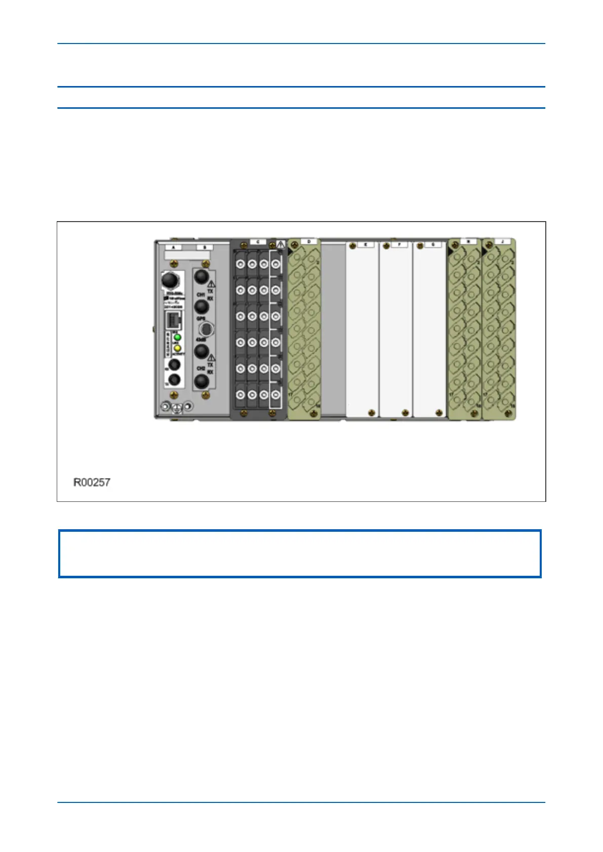
terminal blocks needed to populate the case. The following diagram shows a typical rear view of a case populated
with various boards.
Figure 8: Rear view of populated case
Note:
This diagram is just an example and may not show the exact product described in this manual. It also does not show the full
range of available boards, just a typical arrangement.
Not all slots are the same size. The slot width depends on the type of board or terminal block. For example, HD
(heavy duty) terminal blocks, as required for the analogue inputs, require a wider slot size than MD (medium duty)
terminal blocks. The board positions are not generally interchangeable. Each slot is designed to house a particular
type of board. Again this is model-dependent.
The device may use one or more of the terminal block types shown in the following diagram. The terminal blocks
are fastened to the rear panel with screws.
● Heavy duty (HD) terminal blocks for CT and VT circuits
● Medium duty (MD) terminal blocks for the power supply, opto-inputs, relay outputs and rear
communications port
● MiDOS terminal blocks for CT and VT circuits
● RTD/CLIO terminal block for connection to analogue transducers
P543i/P545i Chapter 3 - Hardware Design
P54x1i-TM-EN-1 41

 Loading...


