EasyManuals Logo
Home>GE>Control Unit>MiCOM P40 Agile

GE MiCOM P40 Agile User Manual

GE MiCOM P40 Agile
802 pages
To Next Page IconTo Next Page
To Previous Page IconTo Previous Page
Page #396 background imageLoading...
Page #396 background image
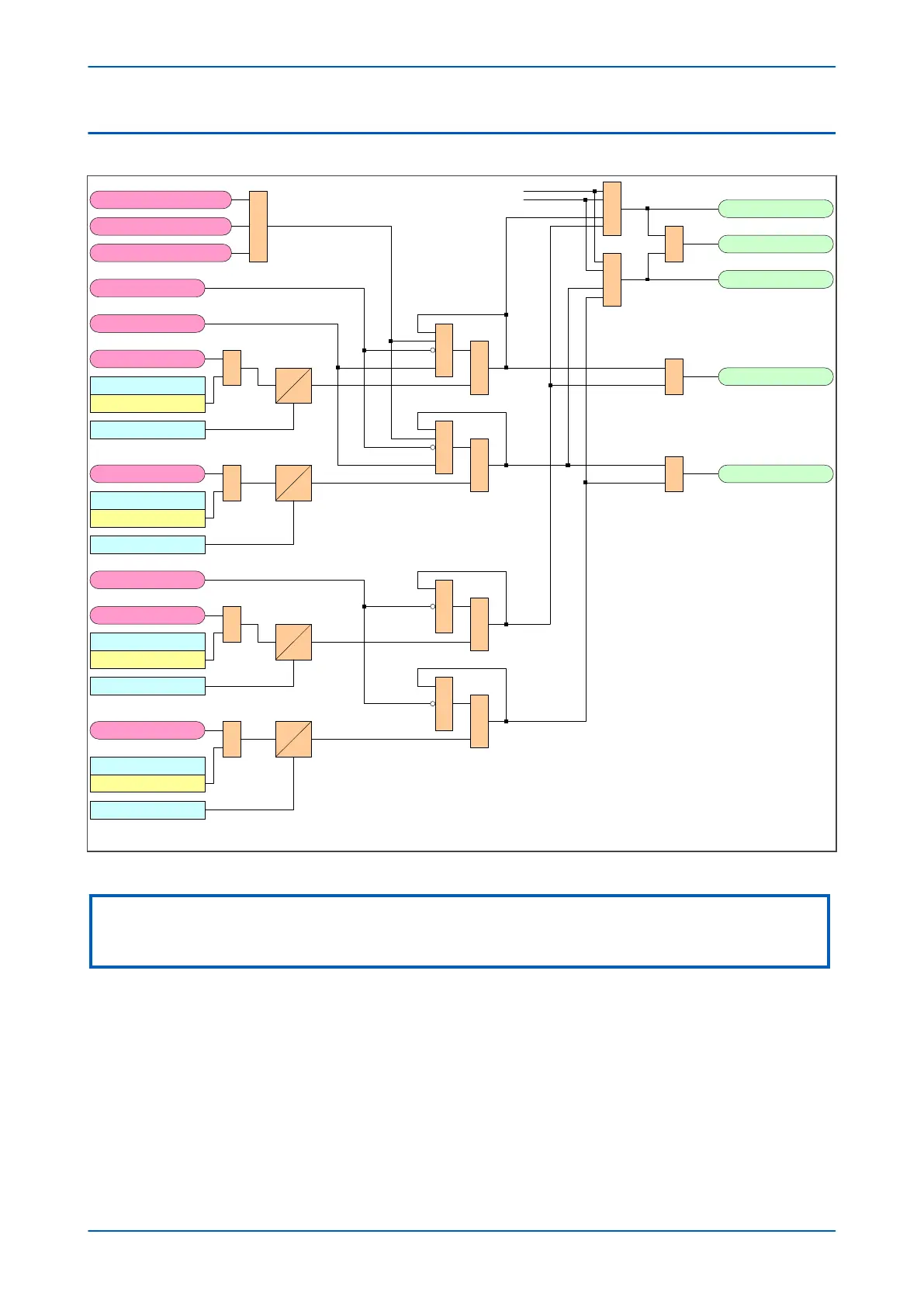
4.4 CIRCUIT BREAKER FAIL LOGIC - PART 4
V00732
1
&
1
CB Fail1 Trip A
CBZCDStateA
WIINFEEDA
TripStateA
Bfail1 Trip 3ph
CB Fail Alarm
Bfail2 Trip 3ph
1
1
1
From phase B equivalent
From phase C equivalent
LatchATripResetIncomp*
1
1
Latch3PhTripResetIncomp
LatchNonITripResetIncomp
&
CB Fail 1 Status
Enabled
CB Fail 1 Timer
1
&
1 CB Fail2 Trip ATripStateA
&
CB Fail 2 Status
Enabled
1
&
ZCDStateSEF
TripStateSEF
&
CB Fail 1 Status
Enabled
1
&
TripStateSEF
&
CB Fail 2 Status
Enabled
*1: Not used in P445.
CB Fail 1 Timer
t
t
t
t
0
0
0
0
CB Fail 2 Timer
CB Fail 2 Timer
Figure 211: Circuit Breaker Fail logic - part 4
Note:
This diagram shows only phase-A for a single-CB device. The diagrams for phases B and C follow the same principle and are
not repeated here.
Chapter 12 - CB Fail Protection P543i/P545i
360 P54x1i-TM-EN-1

Table of Contents

Questions and Answers:

Question and Answer IconNeed help?

Do you have a question about the GE MiCOM P40 Agile and is the answer not in the manual?

GE MiCOM P40 Agile Specifications

General IconGeneral
BrandGE
ModelMiCOM P40 Agile
CategoryControl Unit
LanguageEnglish

Related product manuals