3 INDEPENDENT R.O.C.O.F PROTECTION
Where there are very large loads, imbalances may occur that result in rapid decline in system frequency. The
situation could be so bad that shedding one or two stages of load is unlikely to stop this rapid frequency decline. In
such a situation, standard underfrequency protection will normally have to be supplemented with protection that
responds to the rate of change of frequency. An element is therefore required which identifies the high rate of
decline of frequency, and adapts the load shedding scheme accordingly.
Such protection can identify frequency variations occurring close to nominal frequency thereby providing early
warning of a developing frequency problem. The element can also be used as an alarm to warn operators of
unusually high system frequency variations.
3.1
INDEPENENT R.O.C.O.F PROTECTION IMPLEMENTATION
The device provides four independent stages of protection. Each stage can respond to either rising or falling
frequency conditions. This depends on whether the frequency threshold is set above or below the system nominal
frequency. For example, if the frequency threshold is set above nominal frequency, the rate of change of frequency
setting is considered as positive and the element will operate for rising frequency conditions. If the frequency
threshold is set below nominal frequency, the setting is considered as negative and the element will operate for
falling frequency conditions.
The function uses the following settings (shown for stage 1 only - other stages follow the same principles).
● df/dt Avg.Cycles calculates the rate of change of frequency over a fixed period of several cycles.
● df/dt>1 Status: determines whether the stage is for falling or rising frequency conditions
● df/dt>1 Setting: defines the rate of change of frequency pickup setting
● df/dt>1 Time: sets the time delay
● df/dt>1 Dir'n: sets the direction of change you wish to check (positive, negative, or both)
In addition, start, trip and timer block DDB signals are available for each stage, as well as an inhibit signal to inhibit
all four stages.
3.2
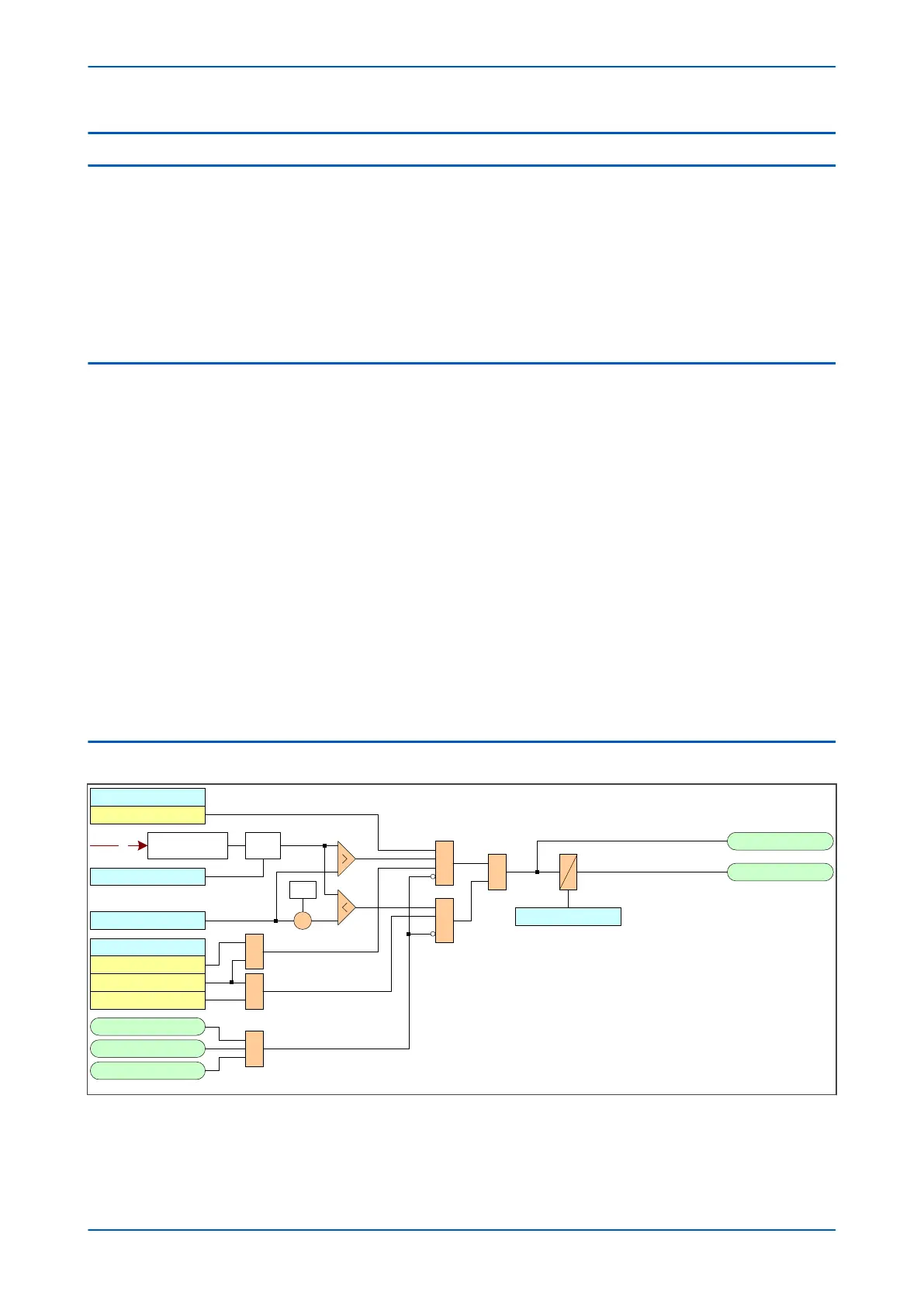
INDEPENDENT R.O.C.O.F PROTECTION LOGIC
V00869
V
df/dt Avg. Cycles
-1
×
Frequency
determination
df/dt
df/dt>1 Setting
&
&
1
df/dt>1 Trip
df/dt>1 Start
df/dt>1 Time
df/dt>1 Status
Enabled
df/dt>1 Dir’n
Negative
Positive
Both
1
1
Freq Not Found
Freq High
Freq Low
1
1370
1368
1369
597
601
Figure 239: Rate of change of frequency logic (single stage)
P543i/P545i Chapter 15 - Frequency Protection Functions
P54x1i-TM-EN-1 415

 Loading...


