2 INTRODUCTION TO POWER SWING BLOCKING
Power swings are variations in power flow that occur when the voltage phase angles at different points of
generation shift relative to each other. They can be caused by events such as fault occurrences and subsequent
clearance. Power swings may be classified as stable or unstable.
A stable power swing is one where, following a disturbance, all sources of generation return to a state where they
are all generating synchronous voltages. An unstable power swing is one where at least one source of generation
cannot restore operation that is synchronous with the rest of the system. In this case the poles of one source of
generation slip with respect to those of another. This condition is known as Pole Slipping.
A power swing may cause the impedance presented to Distance protection to move away from the normal load
area and into one or more of its tripping characteristics. Without attention this could lead to unwanted or
uncontrolled tripping.
Note:
Power swings do not involve earth, so only phase-phase impedances are affected.
For stable power swings, distance protection should not trip. To prevent tripping, a Power Swing Blocking (PSB)
function is usually provided to compliment Distance protection.
For unstable power swings, there may be a strategy for instigating a controlled system split. In this case, distance
protection should not trip during loss of stability. If unstable power swings or Pole-Slipping conditions might be
expected, certain points on the network may be designated as split points, where the network should be split if
unstable (or potentially unstable) conditions occur. Strategic splitting of the system can be achieved by means of
dedicated Out-of-Step Tripping protection (OOS or OST protection). Or it may be possible to achieve splitting by
strategically limiting the duration for which the operation of a specific distance protection is blocked during power
swing conditions.
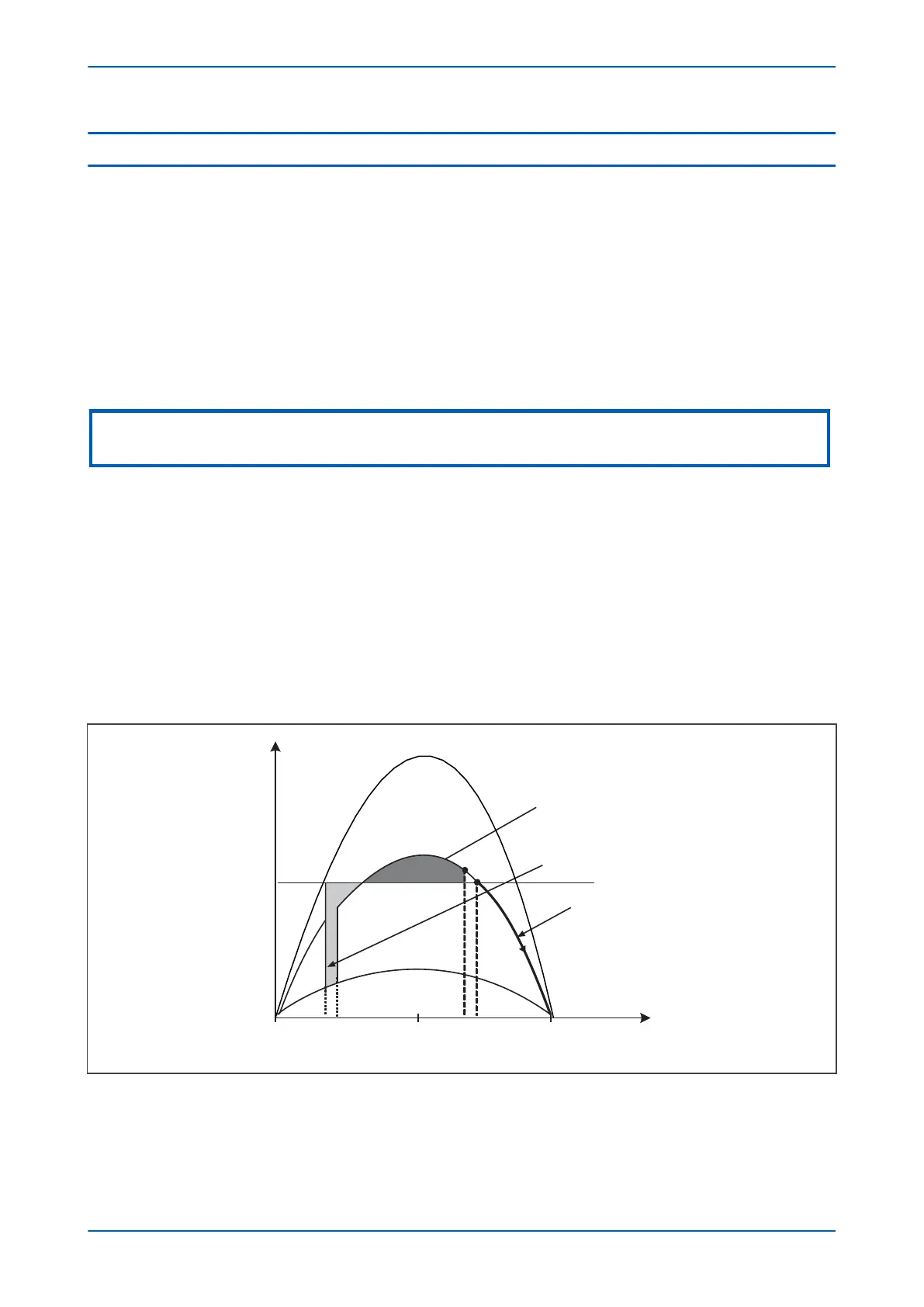
A method often used to help understand power system stability and Pole Slipping is called Equal Area Criterion.
This is based on a number of operational curves as outlined in the figure below:
V02762
Curve 1
Curve 2
Curve 3
Area 1
Area 2
Out of step
Phase angle difference between two ends
Power
F
GEA
D
C
B
θ
0
θ
1
θ
2
θ
3
θ
Po
0º 90º 180º
Figure 148: Power transfer related to angular difference between two generation sources
Chapter 10 - Power Swing Functions P543i/P545i
270 P54x1i-TM-EN-1

 Loading...


