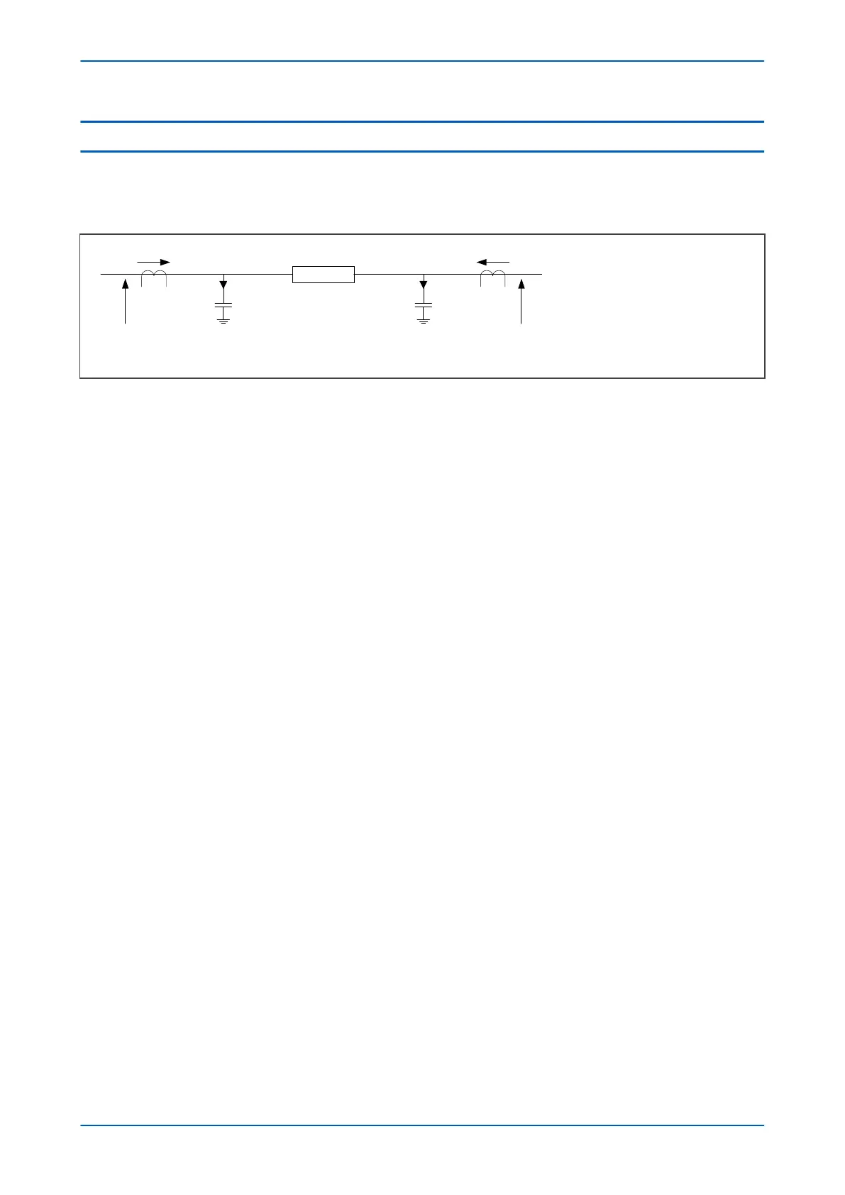
8 CAPACITIVE CHARGING CURRENT COMPENSATION
All electrical conductors, including feeders, are capacitively coupled to earth. When energised, a capacitive current
flows from the feeder to earth to charge the capacitance. The capacitance is distributed along the feeder, but for
analysis it can be modelled according with the following figure.
V02608
V
L
ZL I
L
= Local end line current
I
R
= Remote end line current
VL = Local end voltage
VR = Remote end voltage
Z
L
= Line impedance
I
CHL
= Local end charging current
I
CHR
= Remote end charging current
V
R
I
CHL
I
CHR
I
L
I
R
Figure 38: Capacitive charging current
Both transient capacitive and steady-state capacitive charging currents exist. Transient inrush charging current
consists of predominately high-order harmonics, which are filtered out by the device. However, steady state AC
charging currents flow all the time that the feeder remains energised. This capacitive charging current appears as
a differential current. On long overhead lines, and on cable circuits, this capacitive charging current can be
sufficiently high to cause current differential elements to trip under healthy conditions and therefore needs to be
compensated.
To prevent maloperation due to capacitive charging currents, Phase Is1 would normally be set to at least 2.5 times
the charging current. This, however, reduces the sensitivity of the differential protection. If voltage input
connections are made, more effective compensation for capacitive charging current can be applied:
Using the voltage inputs and the line positive-sequence capacitive susceptance, the devices can calculate the
charging currents. These can then be taken into account before calculating the differential currents.
Referring to the figure above, we see that the line charging current at a particular location is equal to the voltage
at that location multiplied by the line positive sequence capacitive susceptance (Bs). The differential current is
therefore:
I
di
= I
L
+ I
R
- (jV
LBs
/2) - (jV
RBs
/2) = {I
L
- (jV
LBs
/2)} + {I
R
- (jV
RBs
/2)}
The two terms in this equation represent one component that can be calculated at a local terminal and another
that can be calculated at a remote terminal. Using these values, rather than the actual phase current
measurements, will eliminate the effects caused by capacitive charging currents. So, for long line or cable
applications, if voltage transformers are connected, capacitive charging current compensation can be applied.
This is achieved by setting the Compensation setting in the CURRENT DIFF column to Cap Charging. This will
make visible a Susceptance setting into which the line positive sequence capacitive susceptance value can be
entereed.
When applied to a three-ended scheme with ends local (L), remote 1 (R1) and remote 2 (R2), the differential current
is calculated as:
I
di
= I
L
+ I
R1
+ I
R2
- (jV
L Bs
/3) - (jV
R1Bs
/3) - (jVR
2Bs
/3) = {I
L
- (jV
LBs
/3) } + {I
R1
- (jV
R1Bs
/3) } + {I
R2
-
(jV
R2Bs
/3)}
If the capacitive charging compensation is enabled, the current measurements in the MEASUREMENTS 3 column
display the compensated values.
Chapter 6 - Current Differential Protection P543i/P545i
112 P54x1i-TM-EN-1

 Loading...


