Terminal Number Output Relay
Terminal 11 Relay 6 NO
Terminal 12 Relay 6 NO
Terminal 13 Relay 7 changeover
Terminal 14 Relay 7 changeover
Terminal 15 Relay 7 common
Terminal 16 Relay 8 changeover
Terminal 17 Relay 8 changeover
Terminal 18 Relay 8 common
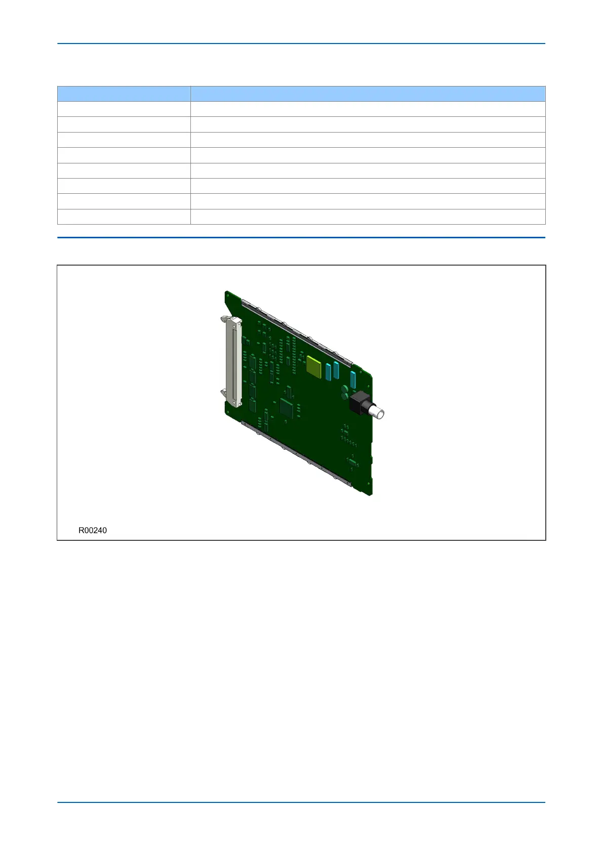
6.7 IRIG-B BOARD
Figure 22: IRIG-B board
The IRIG-B board can be fitted to provide an accurate timing reference for the device. The IRIG-B signal is
connected to the board via a BNC connector. The timing information is used to synchronise the IED's internal real-
time clock to an accuracy of 1 ms. The internal clock is then used for time tagging events, fault, maintenance and
disturbance records.
IRIG-B interface is available in modulated or demodulated formats.
The IRIG-B facility is provided in combination with other functionality on a number of additional boards, such as:
● Fibre board with IRIG-B
● Second rear communications board with IRIG-B
● Ethernet board with IRIG-B
● Redundant Ethernet board with IRIG-B
There are two types of each of these boards; one type which accepts a modulated IRIG-B input and one type
which accepts a demodulated IRIG-B input.
Chapter 3 - Hardware Design P543i/P545i
54 P54x1i-TM-EN-1

 Loading...


