+R
+jX
V02735
R’
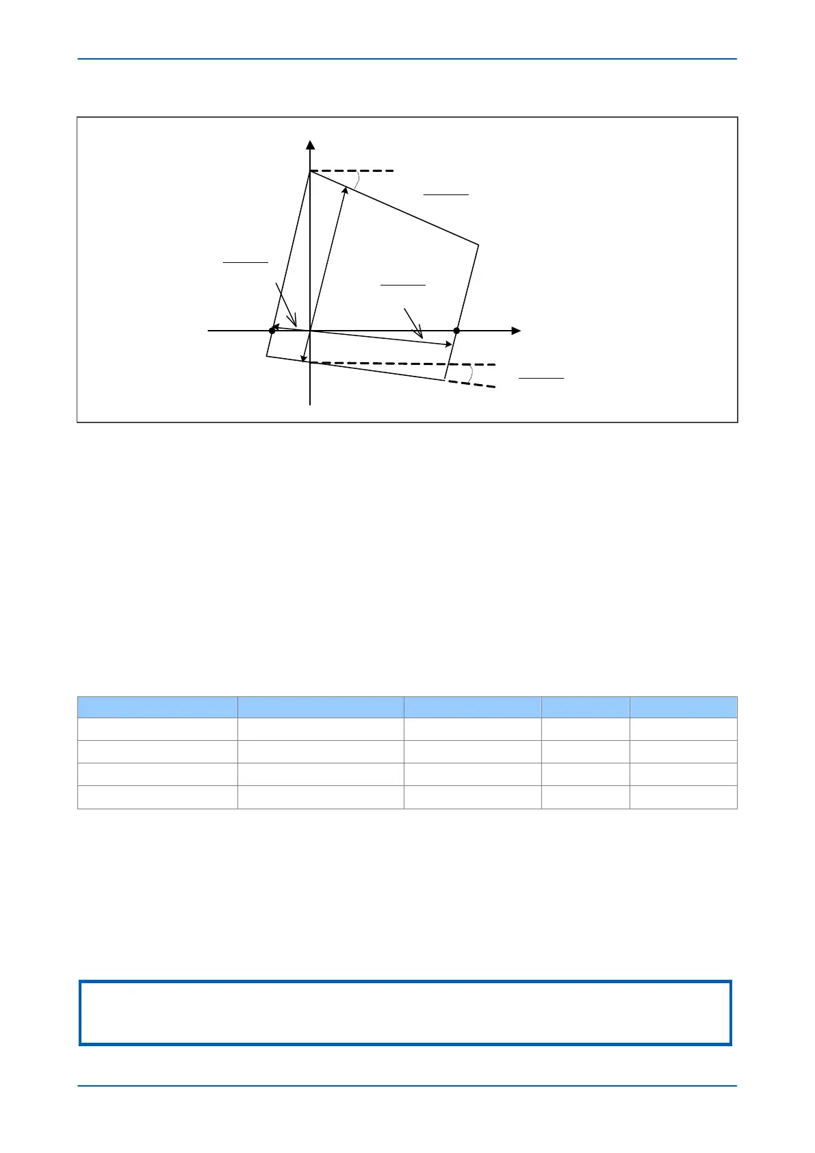
reach
Z’
Z
1
plane
Z
R
reach
Figure 70: Simplified characteristic in Z1 plane
R
reach
= ((RLP./(1 + k
ZN
)).sin( Z +
a
)),
R’reach = ((R’LP./(1 + k
ZN
)).sin( Z +
a
)),
where: a is the angle of 1/(1 + k
ZN
):
a
= (1/(1 + k
ZN
))
In typical cases the sine ratio coefficient term is close to unity so the simplified equations can be used:
R
reach
= R
LP
/ ǀ (1 + k
ZN
) ǀ,
R’
reach
= R’
LP
/ ǀ (1 + k
ZN
) ǀ,
So in terms of replica impedances and loop resistances, the comparators used for the resistance lines are as per
the following table:
Zone Line S1 S2 Condition
Forward or Offset Resistive reach
Vph - Iph.R
LP
Iph.Z
replica
∠S1 -∠S2 > 0º
Forward or Offset Reverse resistive reach
Vph - Iph.R’
LP
Iph.Z
replica
∠S1 -∠S2 < 0º
Reverse Resistive reach
Vph + Iph.R
LP
-Iph.Z
replica
∠S1 -∠S2 > 0º
Reverse Reverse resistive reach
Vph + Iph.R’
LP
-Iph.Z
replica
∠S1 -∠S2 < 0º
The Resistive Impedance Reach side of the earth zone is controlled by the Resistive Reach setting applied (Rx Gnd
Resistive). This defines the fault arc resistance that can be detected for a single phase-earth fault. For such a fault,
the fault resistance appears in the total fault loop (out and return loop), in which the line impedance is Z
1
x (1 +
k
ZN
), if IN @ Iph.
Most injection test sets plot impedance characteristics in positive sequence terms, so that the right-hand intercept
appears less than the setting applied (Rn Gnd Resistive /(1+ k
ZN
)). The left hand side is set by the Rn Gnd Res Rev
setting and acts similarly.
Note:
The resistive reach lines of earth-fault Quadrilateral characteristics are not affected by the type of tilting used by the reactive
lines (fixed or dynamic), nor by the angle values.
P543i/P545i Chapter 7 - Distance Protection
P54x1i-TM-EN-1 161

 Loading...


