3.3 NPSOC LOGIC
&
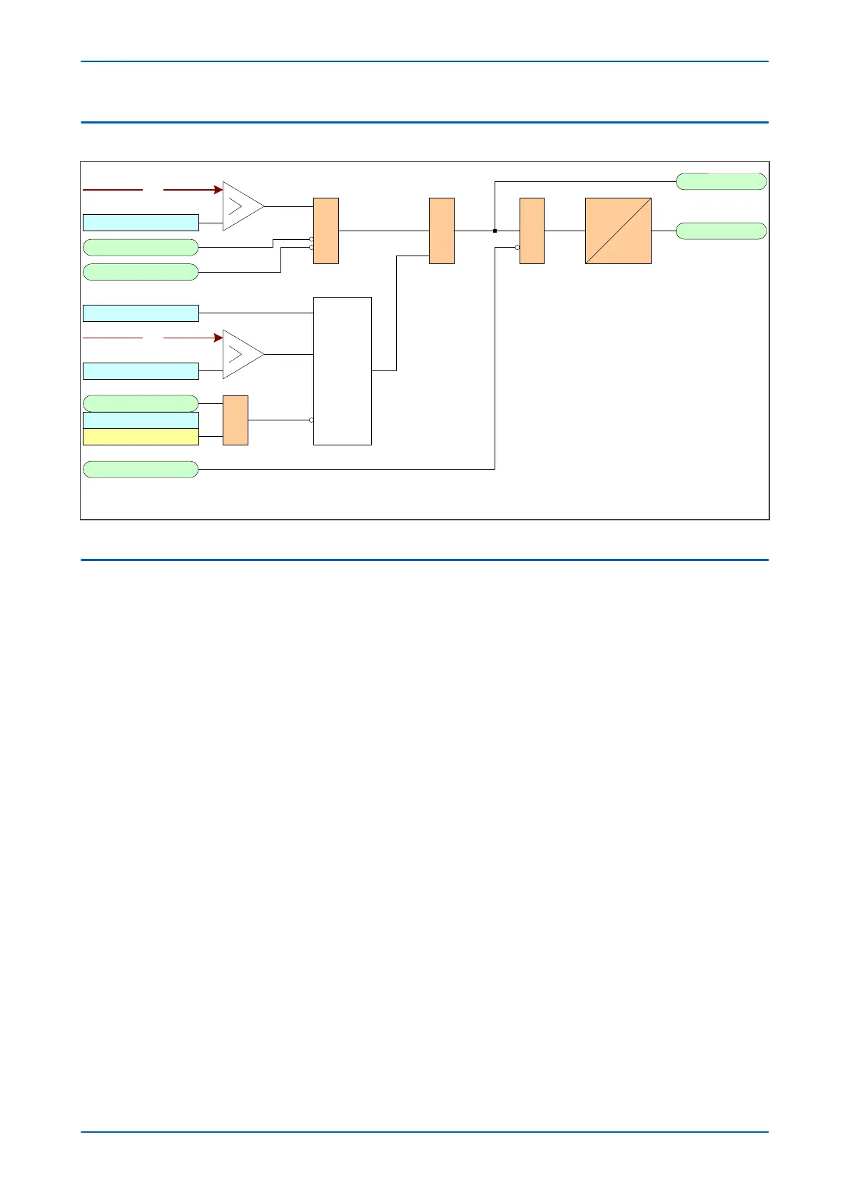
I2>1 Tmr Blk
I2>1 Start
I2>1 trip&
V00736
I2
I2> Inhibit
CTS Block
VTS Slow block
I2> VTS Blocking
VTS Blocks I2>1
V2
I2>1 Current Set
I2> V2pol Set
&
IDMT/DT
Directional
check
&
I2>1 Direction
Note : For the purpose of clarity , this diagram shows the first
relevant stage number for each signal and setting name .
928
562
833
563
567
571
Figure 214: Negative Phase Sequence Overcurrent Protection logic diagram
3.4
APPLICATION NOTES
3.4.1 SETTING GUIDELINES (CURRENT THRESHOLD)
A negative phase sequence element can be connected in the primary supply to the transformer and set as
sensitively as required to protect for secondary phase-to-earth or phase-to-phase faults. This function will also
provide better protection than the phase overcurrent function for internal transformer faults. The NPS overcurrent
protection should be set to coordinate with the low-side phase and earth elements for phase-to-earth and phase-
to-phase faults.
The current pick-up threshold must be set higher than the negative phase sequence current due to the maximum
normal load imbalance. This can be set practically at the commissioning stage, making use of the measurement
function to display the standing negative phase sequence current. The setting should be at least 20% above this
figure.
Where the negative phase sequence element needs to operate for specific uncleared asymmetric faults, a precise
threshold setting would have to be based on an individual fault analysis for that particular system due to the
complexities involved. However, to ensure operation of the protection, the current pick-up setting must be set
approximately 20% below the lowest calculated negative phase sequence fault current contribution to a specific
remote fault condition.
3.4.2
SETTING GUIDELINES (TIME DELAY)
Correct setting of the time delay for this function is vital. You should also be very aware that this element is applied
primarily to provide back-up protection to other protection devices or to provide an alarm. It would therefore
normally have a long time delay.
The time delay set must be greater than the operating time of any other protection device (at minimum fault level)
that may respond to unbalanced faults such as phase overcurrent elements and earth fault elements.
Chapter 13 - Current Protection Functions P543i/P545i
370 P54x1i-TM-EN-1

 Loading...


