V02773
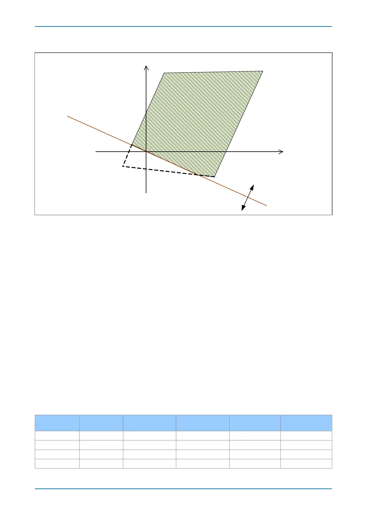
Forward direction
Reverse direction
jX
-jX
Directional Line
R
-R
Figure 64: Five-sided polygon formed by Quadrilateral characteristic with Directional-Line intersection of
Reverse Impedance Reach Line
The applied settings will determine the intersection point. When the settings have been chosen, the following
values will affect the line intersection point:
● Impedance Reach
● Reverse Impedance Reach
● Resistive Reach
● Reverse Resistive Reach
● Directional Line Angle
● Zone Characteristic Impedance Angle
● Tilt Angles of Impedance Reach Lines
The Impedance Reach, the Resistive Reach, and the Zone Characteristic Impedance Angle, can be freely assigned.
The Directional Line Angle is 60º by default but can be varied if the Delta Directional element is enabled. The Tilt
Angle of the impedance lines has a default setting of -3º, but some variation is allowed if the Advanced setting
option is chosen.
The Reverse Impedance Reach, and the Reverse Resistive Reach are applied as a fixed ratio of the Impedance
Reach and the Resistive Reach for Directional characteristics. The ratios used vary according to the zone type. The
following tables present the different values for phase-phase characteristics and phase-earth characteristics. For
completion, the reach limit values for Offset zones are also included (although the overlaid Directional line does not
apply and the Offset characteristics will always be quadrilateral).
Phase-to-phase Element Reaches
Zone
Type Impedance Reach Z
Reverse Impedance
Reach Z’
Resistive Reach R
Reverse Resistive
Reach R’
1 Ph-Ph Forward Z1 Ph. Reach 0.25 Z ½*R1 Ph. Resistive 0.25 R
2 Ph-Ph Forward Z2 Ph. Reach 0.25 Z ½*R2 Ph. Resistive 0.25 R
3 Ph-Ph Forward Z3 Ph. Reach 0.25 Z ½*R3 Ph. Resistive 0.25 R
3 Ph-Ph Reverse Z3 Ph. Reach 0.25 Z ½*R3 Ph. Resistive 0.25 R
P543i/P545i Chapter 7 - Distance Protection
P54x1i-TM-EN-1 153

 Loading...


