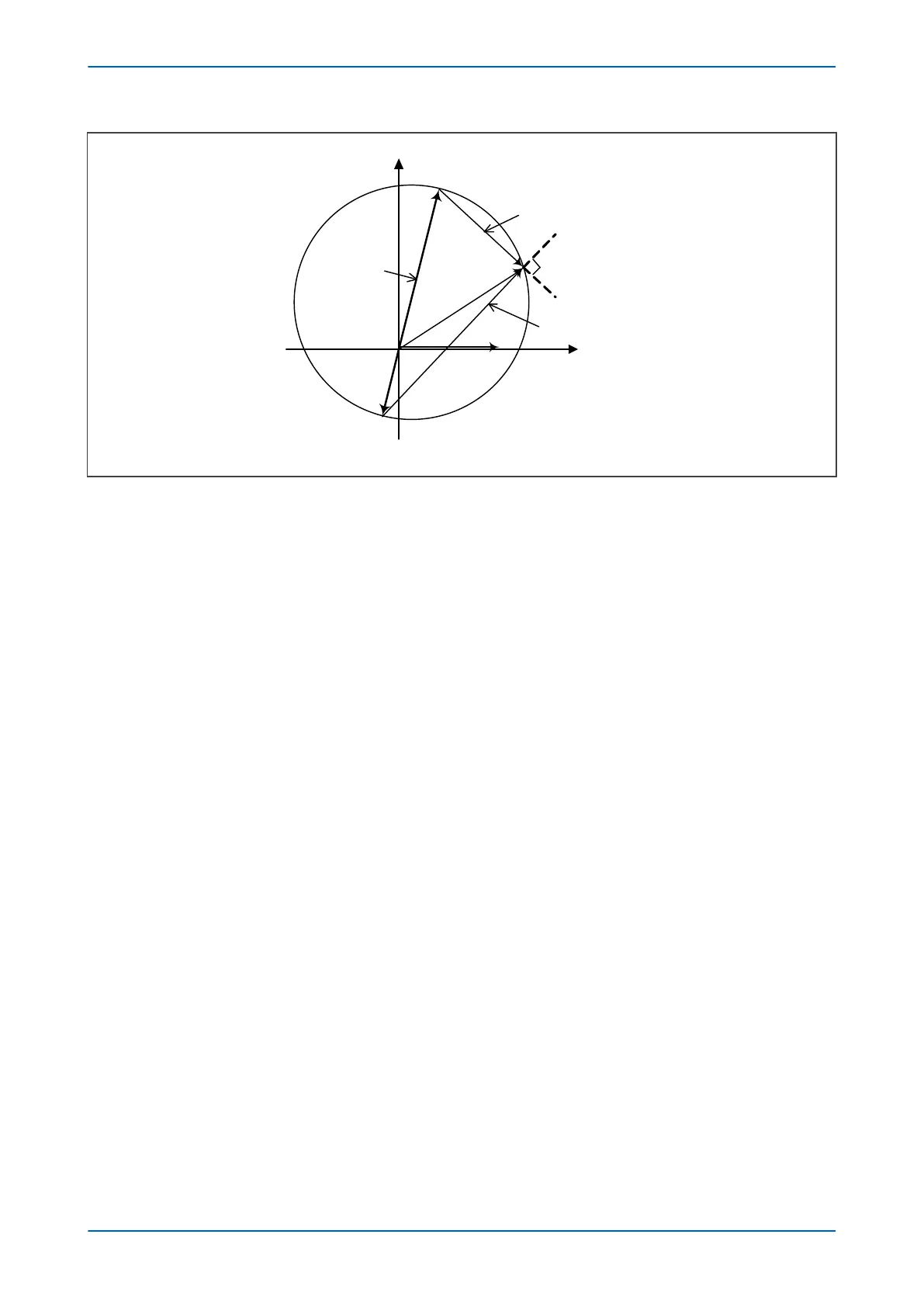
Figure 52: Offset Mho characteristic
The two signals provided to the comparator are:
S
1
= V - IZ'
S
2
= V - IZ
Operation occurs when the angle between the signals is greater than 90°
3.1.3
DIRECTIONAL SELF-POLARIZED MHO CHARACTERISTIC FOR EARTH FAULTS
Characteristics of earth-fault elements can be represented in two different complex planes - the positive sequence
impedance plane (Z
1
-plane) and the loop impedance plane (Z
LP
-plane). The reach impedance setting defines the
reach in positive sequence impedance terms. The characteristic in the Z
LP
-plane is generally dynamic because it
depends on fault currents. However, the Z
LP
–plane representation is often more convenient for reference,
especially if an injection test kit is used, which cannot apply the residual compensation to the impedance plot, or in
the case that the load blinders have to be verified.
The following diagram illustrates how a directional Mho characteristic for earth-faults is created.
Chapter 7 - Distance Protection P543i/P545i
140 P54x1i-TM-EN-1

 Loading...


