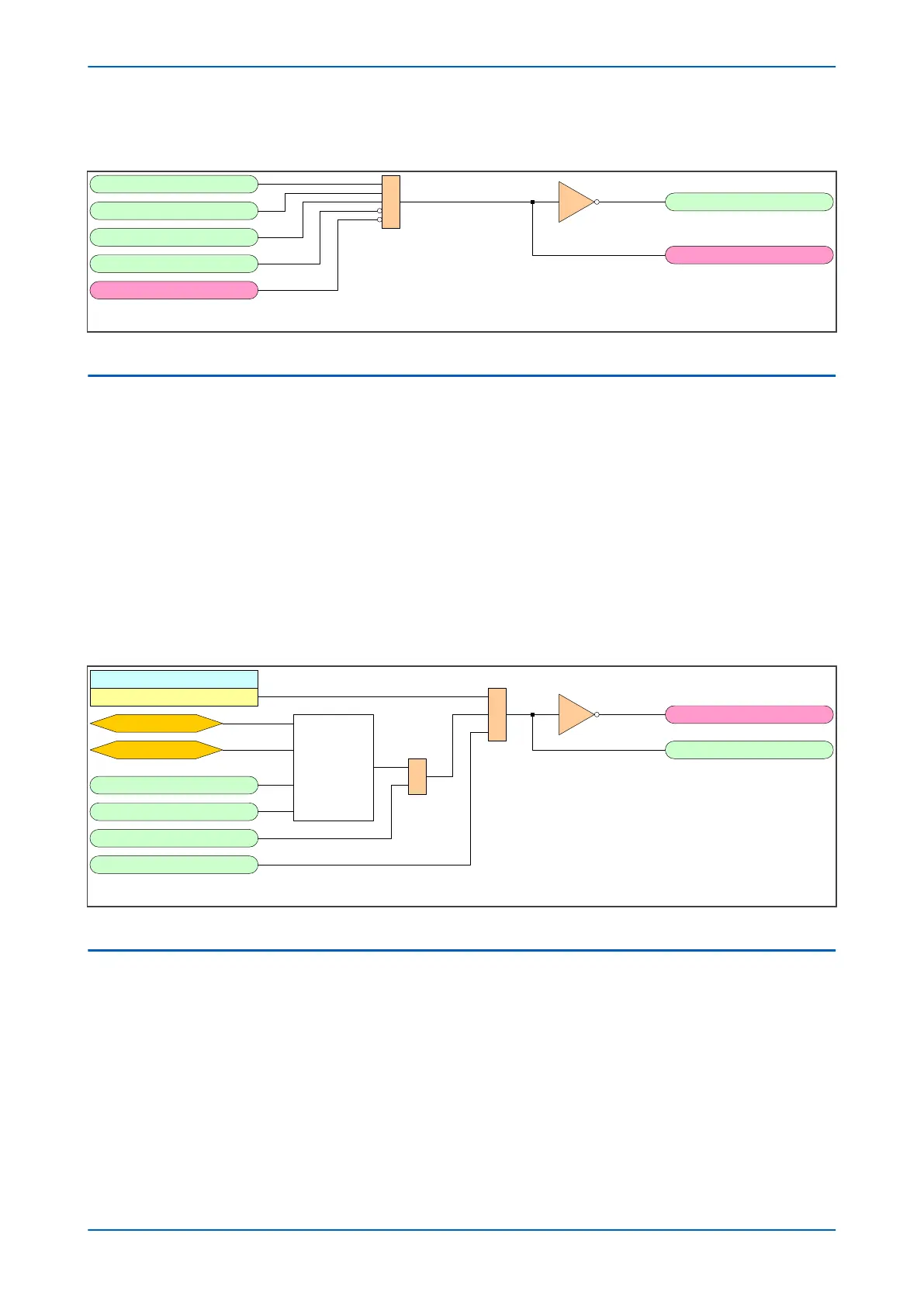
5.3.2 AUTORECLOSE OK LOGIC DIAGRAM
V03308
&
AR In Service
AR Enable CB
CB In Service
A/R Lockout
CB1 AR OK
CB NoAR
BAR CB1
Figure 175: Autoreclose OK logic diagram (Module 8)
5.4
AUTORECLOSE ENABLE
The Autoreclose function must be enabled in the CONFIGURATION column before it can be brought into service. It
can be brought into service by:
● using an opto-input mapped to the AR Enable DDB signal
● pulsing the DDB signal AR Pulse On (use AR Pulse Off to bring it out of service)
● programming a function key on the HMI.
● if applicable, using IEC 60870-5-103 communications
A further validation signal is also required to switch on Autoreclose. This is the DDB signals AR Enable CB. Once
Autoreclose is in service, the AR In Service DDB signal is asserted and the AR Status cell in the CB CONTROL
column is set accordingly.
5.4.1
AUTORECLOSE ENABLE LOGIC DIAGRAM
V03300
Auto-Reclose
Enabled
&
AR On Pulse
AR OFF Pulse
Autoreclose
Status
Default = ON
1
AR Enable
AR Enable CB *
AR DISABLED
AR In Service
HMI Command
IEC 60870 Command
*Defaults to High if not mapped in PSL
Figure 176: Autoreclose Enable logic diagram (Module 5)
5.5
AUTORECLOSE MODES
The device can provide Single-phase and/or Three-phase Autoreclose. The Autoreclose mode is configured by the
AR Mode setting in the AUTORECLOSE column. You can choose from:
● Single-phase (AR 1P)
● Three-phase (AR 3P)
● Single-phase and Three-phase (AR 1/3P)
● Controlled by commands from DDB signals that must be mapped to opto-isolated inputs in the PSL (AR
Opto).
Chapter 11 - Autoreclose P543i/P545i
320 P54x1i-TM-EN-1

 Loading...


